When people think of churches, what often comes to mind is a square white building with a triangular roof and a steeple on top. When the congregation of The United Methodist Church of the Resurrection envisioned its new place of worship, they imagined something much different.
With a growing community of more than 20,000 parishioners in the Kansas City area, the church was bursting out of its existing facilities. The congregation needed a new community space to physically accommodate its members as well as provide space for their ministry’s future growth. At the same time, they also needed a gathering place that continued to convey the sacredness and devotion of the congregation in an intimate setting. To make this vision a reality, the design team was faced with the seemingly impossible task of designing a church that could seat more than 3,500 people and simultaneously convey a sense of intimate sanctuary. With the latest design and modeling tools in hand, the skilled project team accepted the challenge and delivered an awe-inspiring structure for current and future generations of worshippers.
“Mega Church without the Mega Church Feel”
Founded in 1990, the Church of the Resurrection has grown to be the largest United Methodist Church in the United States. The church has four campuses in and around downtown Kansas City, with the main campus located on 76 acres in Leawood, Kan. Every weekend across the four campuses, there are 16 regularly scheduled services attended by many of the more than 20,000 members. By any definition, this is a “mega church.”
According to church leaders, “buildings are tools for ministry” that help fulfill the church’s vision. When the new sanctuary building at Leawood was contemplated, it became clear to the architectural team that the biggest challenge would be creating a large-capacity church with an intimate feel. The church had to bring the 3,500-strong congregation physically close to the worship leader and have the audio/visual tools necessary to address such a large crowd. At the same time, it had to have a sacredness about it and not feel like a cold auditorium.
“We had to design and build a ‘mega church’ without the ‘mega church’ feel,” says Todd Kraft, project architect with HGA Architects and Engineers (HGA).
Model, Print, Tweak, Repeat
Headquartered in Minneapolis, HGA is a 700-person integrated architecture, engineering and planning firm with eight office locations across the United States. HGA strives to understand its clients’ cultural and business needs to help them realize their visions, and the firm’s multidisciplinary collaboration, knowledge-sharing and design-investigation approach would be vital to this project’s success.
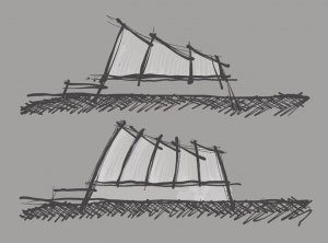
Working in close collaboration with the owners, HGA iterated through dozens of design ideas using BIM, modeling software and 3D printers, all of which have been standard tools in their toolbox for years. According to Nat Madson, design architect with HGA, the team worked with digital tools from the earliest stages.
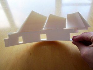
“Our ‘hand sketches’ were done digitally,” notes Madson. “We’d work with our conceptual ideas to create digital models in Rhino. Then, using Grasshopper, we’d take these models to our Stratasys 3D printers and create physical models. We’d use the models for further examination and refinement of ideas and concepts.”
The process was repeated dozens of times, with the building design inching closer to final concept with each iteration.
“Rhino is a great tool because it lets us cycle through options and never gets in the way of what we’re trying to do,” adds Alex Terzich, facade specialist with HGA. Although some firms may be just starting to use digital conceptual models and/or 3D printing, it’s standard operating procedure for HGA. When the digital dust settled and the overall concept for the building coalesced, the architects and owners agreed they had arrived at the best solution.
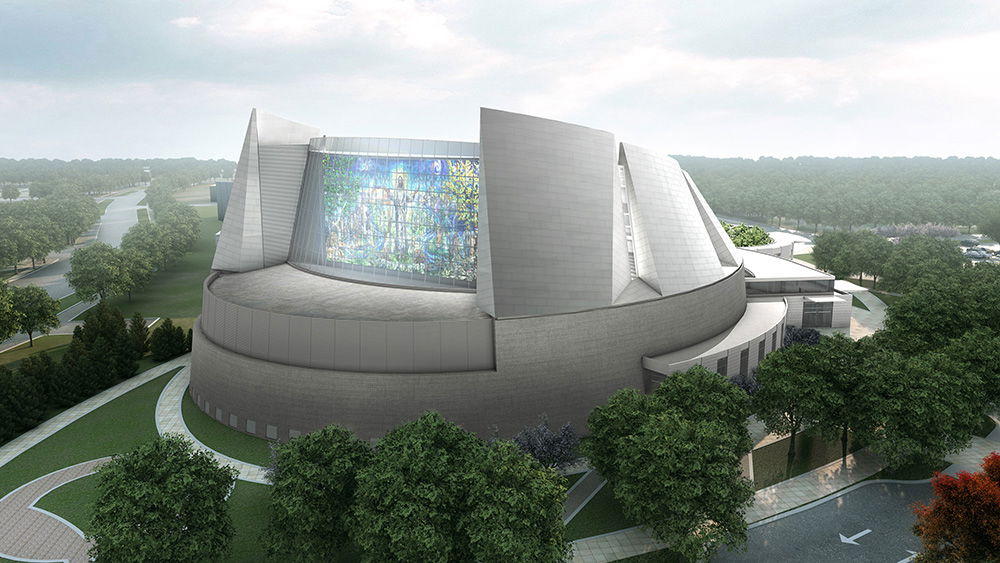
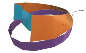
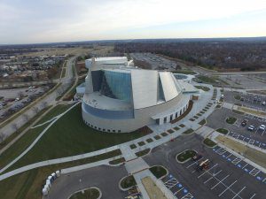
The new sanctuary would be an elliptical building, with inward-sloping steel-supported walls towering 100 feet high, adding a sense of awe and wonder. The base of the steel superstructure is clad in limestone, 35 feet tall. Inside, a thrust-chancel platform and a single balcony bring congregants close to the worship leaders, with a variety of seating types allowing flexibility in service size. More than 90 percent of the 3,500-plus seats are within 100 feet of the chancel.
Rising above the limestone base are seven panels representing various aspects of the church’s beliefs. An eighth panel is The Resurrection Window, telling the story of Easter, the most sacred holiday for Christians. It features a 3,400-square-foot stained glass installation that, when complete, will be one of the largest stained-glass installations in the Midwest. “The documentation of this building using only 2D CAD software would have been almost impossible with such a small team,” adds Terzich.
The team used a hybrid approach to design and modeling.
“We would quickly iterate complex sections in Rhino, trying different ideas and configurations, and then import these models into Revit,” notes Madson. “The data exchange was not without its challenges, but it worked.” Autodesk Revit would be a valuable tool used throughout the design and construction phase, as it was the project database and “common denominator” among the design teams and contractor.
Structural Support
The building’s elliptical shape and the leaning/canted walls and columns resulted in a non-linear layout in horizontal and vertical planes. To design the structural elements to support the complex building geometry would require a wide range of design tools, from the humble spreadsheet to task-specific applications for foundation and roof design (see the list of technology tools at “The Technology Toolbox” on page 22).
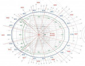
The design team had developed an awe-inspiring, open-yet-intimate sanctuary, and an underlying driver for the engineering team was to create a structure that met the aesthetic goals without being a dominant feature. Adding to the challenges, the engineering team had to design on an elliptical grid driven by the building’s form. Revit was used heavily by the architectural and engineering design teams, but the application doesn’t handle elliptical grid lines. Using an innovative approach, engineers approximated the ellipse using a set of four arcs, allowing them to build grid lines as elements in Revit.
On the plains of Kansas, wind gusts of 80 miles per hour (MPH) are not uncommon and those as high as 109 MPH have been recorded. Intended to last for 100 years or more, the church would be buffeted by lateral and uplift loads for generations. Therefore, a main design challenge involved handling these wind loads on the tall, sloped sanctuary walls. The building’s non-rectilinear shape added to the challenge. Working from Rhino models created by architects, engineers exported the model elements to an Excel spreadsheet where wind vectors were analyzed and lateral loads were calculated.
Below the surface, carrying vertical and lateral loads, the foundation consists of caissons supporting a reinforced concrete mat. The engineers used LPILE from Ensoft Inc., a special-purpose program for analyzing a pile under lateral loading using the p-y method. The program computes deflection, bending moment, shear force and soil response over the length of the pile.
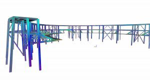
To deliver on the vision of a modern, open gathering space, the structural team had to develop a long-span roof-support system while providing clear views and seating for 3,500 churchgoers. To do this, the engineers used SCIA Engineer’s parameter functionality to set constraints and quickly iterate through truss shapes to optimize the design while setting limits on the maximum allowable depth of the trusses.
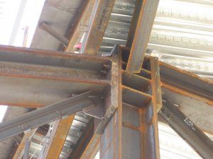
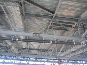
The resulting final design would include six long-span steel-roof trusses, the largest of which is 185 feet long and 15 feet deep. The trusses transfer to the columns a combined live and dead load of 1.95 million pounds. The detailed design of the trusses also accounted for MEP equipment routing by aligning the truss panels to accommodate the HVAC ductwork.
“We like working with SCIA for steel design,” says Sarah Jorczak, associate vice president and lead structural engineer for the project. “It has a robust way of managing loading, which let us perform a thorough design, looking at several alternatives.”
Some Assembly Required
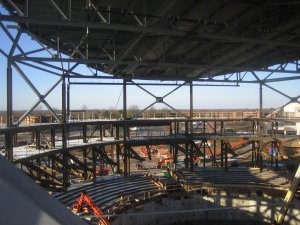
As the main design neared completion, the project focus shifted to the fabrication and erection of the steel components as well as the building’s overall construction. As difficult as it was for the team to design on a non-rectilinear coordinate system, it was all the more challenging for the contractors and fabricators to actually build on that coordinate system. The team relied heavily on modeling and field technology to bring the vision to life.
“We built the structure virtually before building it in the real world,” notes Anthony Van Hoecke, senior project engineer with construction manager with McCownGordon Construction.
The contractor and steel fabricator were brought in during the design-assist phase to provide feedback to engineers. Feedback from the steel erector regarding how they planned on erecting the trusses directly influenced the design. That early planning helped, but there were still many hurdles to overcome.
The building’s elliptical shape presented the team with challenges, and collaboration among all members would be vital to make sure everything came together as planned.
“Have you seen the building?” asks Tab White, vice president of operations with the steel fabricator, Kansas City (KC) Structural. “There isn’t a straight line on it. The first step of our modeling process was a two-week backcheck of HGA’s established grid lines to ensure our anchor bolts and embeds would ‘close’ dimensionally from one side of the [building] to the other. This was further complicated by the need to attach [the new building] to the existing building structure in several planes.”
Working from plans prepared by engineers at HGA, KC Structural created detailed models of the steel structure using Tekla. These models then were exported to DXF and fed into their Peddinghaus plate, beam, and angle line CNC machines to produce parts from standard steel members.
Since there was no horizontal or vertical rectilinear grid, erection crews couldn’t simply pull tape to place the steel or locate connection points. Instead, layout points were set in the 3D model using Trimble Field Link, extracted and uploaded to a Trimble Robotic Total Station (RTS655). Using a Yuma 2 Tablet to control the RTS, the points then were laid out in the field.
“Some points were just out in space, and we had to build to those with no hard reference points,” adds Van Hoecke. This same technique would be used again when it came time for the MEP work.
Due to the design’s complexity, adjustments in the field were inevitable, and the team turned to its technology toolbox to solve the problems.
“All parties involved in the project had their own piece of the puzzle to solve,” notes Kevin Borth, senior associate and structural engineer with HGA. “The [steel] connections were difficult to design for this project.”
Using 3D BIM and working closely with the steel erector and its Tekla model, the team was able to visualize and understand how the pieces would come together.
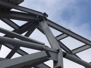
“With a building this complex, the BIM model was indispensable,” states White. “When certain components came in misaligned, we had to make changes in the field to layout the new locations for the ‘sail’ structure anchor pins.” The sail corner bracings were particularly complicated. They consisted of many different steel shapes: HSS, HSSR, double-angle assemblies, wide-flange beams and plates. “The sail corner bracing conditions would make your head spin! But, in the end, everything fit like a champ thanks to the capabilities of the Tekla modeling software.”
Using tablets running Tekla BIMsight, a tool for construction project collaboration that combines multiple models and file formats from a variety of BIM software into one project, the team could assemble 3D models from various applications, define new anchor points in the model and either work directly from the tablet or hardcopy prints. “It’s a great tool, and it’s also free,” adds White.
A Place for Everything
Throughout the construction phase, McCownGordon would host weekly two-hour virtual planning meetings, using BlueJeans video-conferencing technology that connects heterogeneous video-conferencing tools into a single unified platform. The first hour was spent with the design team, MEP subcontractors and the construction manager, working from the ground up to establish phases for erecting the building. The second hour was spent with the MEP subcontractors reviewing clash detections.
In addition to the base Revit model provided by the architect and the structural models from the engineer, each MEP subcontractor had its own BIM team and model. The team at McCownGordon would assemble these various models into a “master” Revit model.
The models created by subcontractors were shared via Box.com, with each sub having its own folder for model files. These individual files then were automatically pulled into Autodesk Navisworks for planning meetings, and the team would use the combined model to focus on the area of interest for the week, planning construction sequencing and reviewing for clashes. This method allowed the team to find issues digitally before they got to the field. Clashes were assigned to individuals to correct prior to construction.
Due to the unique building configuration, installation spaces were very tight. The model was an effective scheduling tool and drove the sequencing of the subs’ various work. The model also helped the team determine which items could be prefabricated. For example, normally McCownGordon would wait until the floors were poured before installing conduit racks. However, using the detailed model, the team determined the conduit racks could be prefabricated and installed prior to the floor pours. This saved a month of installation time. Using the same technique employed to layout the steel-structure connection points, McCownGordon and their subs used the 3D model to determine hanger locations and set northing/easting points. These points then were uploaded to the Trimble equipment for point layout in the field.
The model was used to coordinate installation space for the various systems, with space ownership assigned to the various subs. When conflicts arose in the field, the model was an effective tool in determining who was responsible for correcting the error.
“If there was an unexpected clash, we could all return to the model to determine what items were installed in the wrong location and who was responsible for making changes,” notes McCownGordon’s Van Hoecke. “As such, the model was effective in resolving contract issues.”
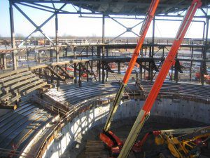
The elliptically curved and stepped seating in the sanctuary forced the construction team to bring additional tools to bear on the project. The mechanical plans called for a diffuser to be placed beneath alternating seats, requiring openings in the concrete floors. To ensure the diffusers were installed in the correct locations, the team used a FARO Focus3D laser scanner to capture point clouds of the concrete seating steps. This information was combined with the seats’ design model; the diffuser locations then were set in the model, uploaded and then laid out in the field.
FARO laser scanning also was used to establish the precise as-built geometry of the two elliptical grand stairs and finalize the ornamental railing shop drawings for the two elliptical cast-in-place concrete exterior stairs.
Celebration Time
The recurring challenge with designing and constructing this project was the elliptical geometry of the new sanctuary. From digital hand sketches to collaborative 3D models to digital point layout and point-cloud capture, modern technology tools were indispensable in making the vision a reality. Construction and buildout continue, and they’re scheduled for completion in time for Easter celebrations in early April 2017.
“The technology speaks for itself,” says McCownGordon’s Van Hoecke. “This project would not have been completed in the required timeframe without it.”

Mark Scacco
Mark Scacco, P.E., is a 25-year veteran of AEC technology and design consulting. He is an AEC Industry Consultant with Scacco LLC and can be reached via email at [email protected].
Video: New Roundabout Under Construction at McIver and Old Florence Roads in Darlington County
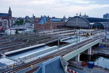
Bridge Replacement at Amsterdam Centraal Station
June Issue 2026
.jpg?width=225)