Deliberate Clashing in Urban Infill Projects
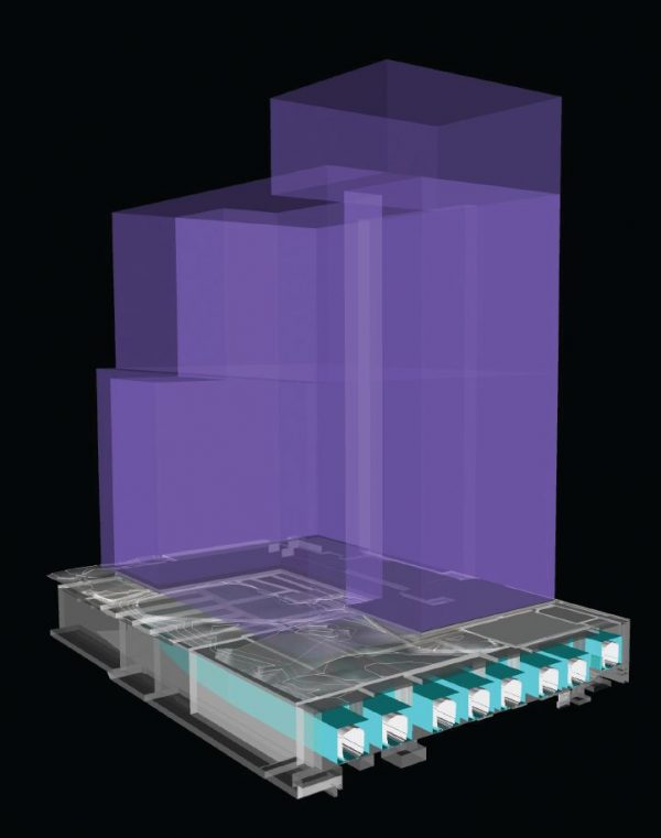
A partial 3D axonometric section shows the representation of an existing railyard with a structural platform built around it as well as the potential massing of a building above. All geometry was created within either AutoCAD or Revit and then imported into Navisworks.
As urban populations grow and demand for housing increases, vacant or underutilized land is at a premium, leading to a rise in urban infill projects. Whenever the needs of a dense population change drastically in a short period of time there is a necessity for new technology and processes and developments that take advantage of huge facilities built in the previous century, such as transportation hubs and industrial centers.
In the United States and Europe, there are notable examples of ongoing urban industrial/transportation infill projects. Brownfield projects such as London’s Battersea Power Station (2012) and Kings Cross development (2007), and Paris’ Rive Gauche project (1995) are being designed to infill the urban voids left by old industrial complexes in inner cities.
In other locations, metropolitan passenger railyards are drawing interest. Still very much in use, they occupy hundreds of acres of prime real estate. Portions of these tracts are either not developed or contain inactive industrial sites. These areas create open voids within our inner cities as well as opportunities. The trains at these sites provide a major mode of transportation for the daily commute of millions of people. Careful advanced planning is essential, however, because it wouldn’t be economically feasible to shutter these transportation services for lengthy periods during construction.
Developers, local governments and public entities can draw upon and evaluate the successes of transforming underutilized urban railyards. As New York City’s Hudson Yards, Pacific Park and Sunnyside Yard projects are tested, proven and refined, cities such as Washington, D.C. (Union Station), Chicago (South Loop) and Philadelphia (Schuylkill Yards) are studying their own plans for constructing around and over the tops of their railyards.
Planning Plus 3D Technology
Redeveloping such properties is complicated. However, with the advent of new, accurate 3D modeling software, architects and engineers can replicate not only the existing site conditions of these railyards, but also the complex transportation systems that use them. For example, think how and where a train moves along a track through a railyard. By merging those concepts with new structures and architecture built around and above railyards and deliberately clashing them, they can carefully plan and design these unique sites in an artificial 3D environment far in advance of construction.
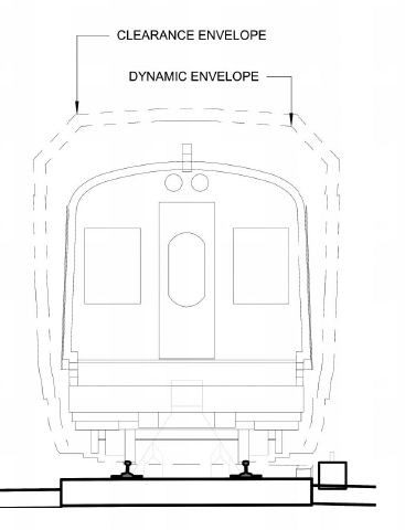
A section of a typical train car shows its dynamic or moving envelope as well as its clearance envelope.
The purpose of utilizing technology to detect clashes in the design phase is to streamline the project process overall. The main difference from how Navisworks software, for example, is most often used in these examples is in mixing new and existing site elements. Usually, construction elements being clashed early in the design process are using hypothetical digital representations of the building design from multiple disciplines (i.e., structure/MEP/architecture) and are easily modified if caught early enough. With an existing transportation system, this is not the case.
By using new mobile 3D laser-scanning technologies, survey engineers can precisely measure and document existing site conditions. They can translate the generated point-cloud data using Autodesk’s Recap software, for example, to visualize and ultimately recreate that geometry in CAD or Revit.
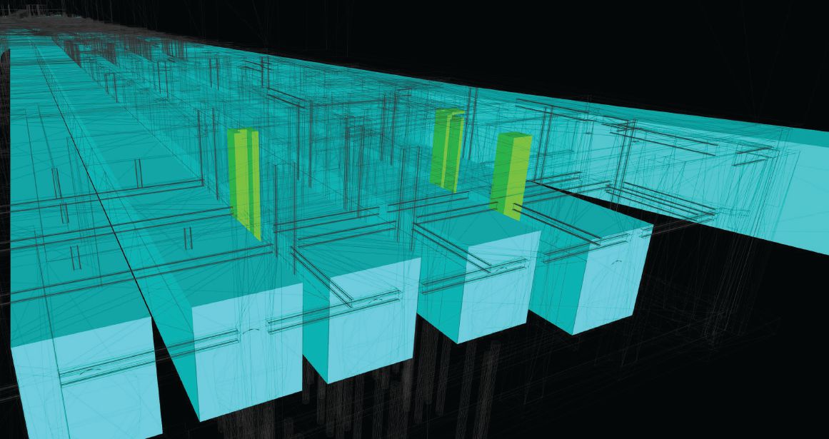
A potential “clearance” clash between train envelope and structural column, as opposed to a “hard” clash where solid geometry might intersect.
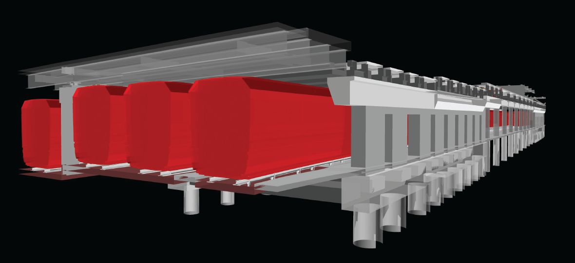
A partial 3D axonometric section describes an existing railyard below as well as the structural platform built above and around it.
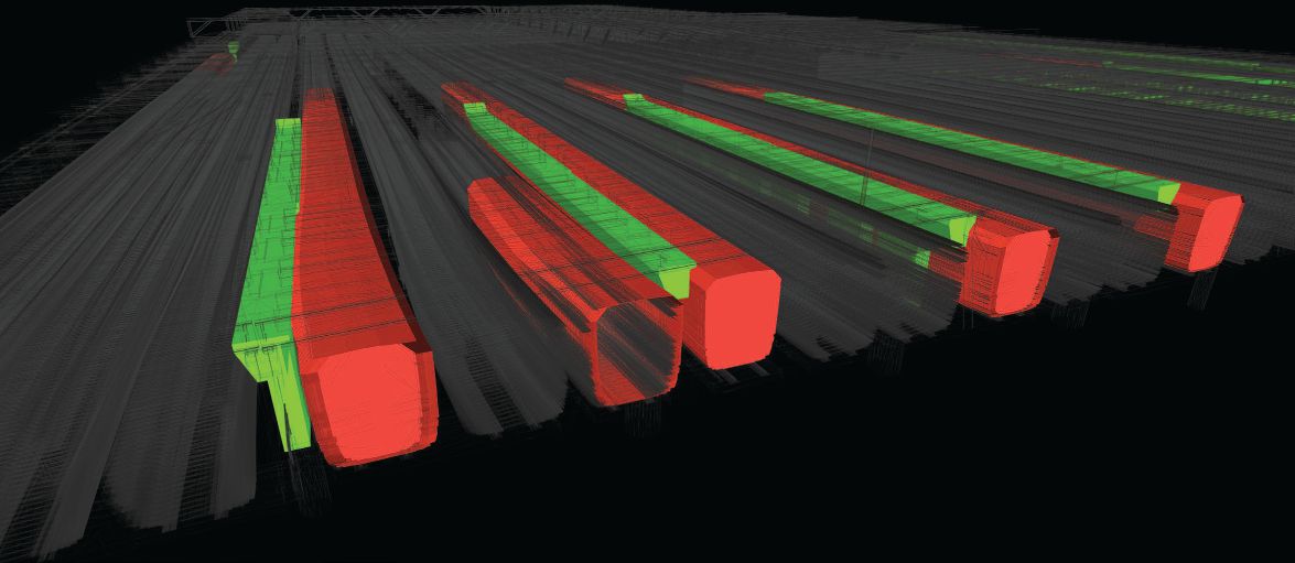
A model shows potential “clearance” and “hard’” clashes between train envelopes and structural beams.
Designing for Deliberate Clashes
Using Navisworks’ clash-detection analysis and accurately modeled geometry from Revit, engineers can identify dimensions down to less than an inch, revealing avoidable real-world conflicts between existing and new objects. An example of this deliberate clash detection is an existing moving train potentially colliding with a new structural column. Train designs comprise not only the physical cab we ride in, but also two invisible and hypothetical spatial offsets from the physical train. Other built objects cannot enter these zones in order for physical clashes to be avoided.
These invisible clearance envelopes can be modeled as solid geometry in Revit and clashed in Navisworks. There’s a static clearance envelope and a dynamic or non-static moving clearance that must be considered. When a train moves along a railway, there’s an expected but very slight “wobble” centered on the train’s axles at the bottom to the top of the train cab. This is referred to as a dynamic clearance envelope. Something as unassuming as the location, or XYZ coordinates of an existing, in-use train rail track can have a domino effect on everything above and around it. Studying these concepts digitally in advance is invaluable for the design process.
Using typical construction methods, this conflict would be discovered in the field manually. It would halt progress for weeks while the incident was documented and sent back to architects and engineers to study and modify the design to resolve the issue.
Identifying Fire-Safety Issues
Another example singularly unique to constructing on top of railyards is fire safety. Although these sites have been open to the air for the last 100-plus years, the concern has been minimal. With planning to enclose a railyard, the risks of fire and smoke ventilation need to be carefully considered to meet even the most basic of local fire codes, often requiring special variances of cities’ fire laws.
Using computer simulations and the aforementioned accurately modeled building and site geometry, precise spatial areas can be calculated to analyze air volumes. This will guide planning for the complex ventilation systems required to safely enclose these spaces and build over the top of them.
Looking to the Future
With advanced, detailed planning and phasing, construction costs and times can potentially be cut in half while the transportation systems experience minimal impact and continue to function normally. Compare Paris’ Rive Gauche redevelopment, which is still under construction more than 20 years later, with Hudson Yards, whose first phase started in 2012 and is already complete. The difference in the progress of these projects is largely due to improvements in design software.
There are positives and negatives to using new technology to deliberately clash design elements before construction. On the negative side, there’s a learning curve—as with all new technology—and periods of trial and error. On the positive side are cost and time savings if implemented early enough and incorporated into a project’s overall design and construction processes.
The utilization of these technologies has only scratched the surface of their total potential impact on the construction industry. The in-progress redevelopment projects have already demonstrated how technology accelerates construction. These projects bring construction jobs that spur local economies, deliver more modern housing and office buildings, and expand the tax base by attracting world-class populations.
About Jason Stevens
Jason Stevens is a Microdesk Strategic BIM Implementation Manager, providing clients with software technical support, technology troubleshooting and best practices advisory services; web: www.microdesk.com.