MBDC is the use and transfer of digital data and information among design and construction to convey design intent, capture as-constructed data, and provide data for asset management. MBDC, including the use of 3D models as legal contract documents, is being deployed on a variety of bridges under design and construction by state Departments of Transportation across the nation. How did the industry get to this point, and what’s still needed to facilitate widespread adoption?
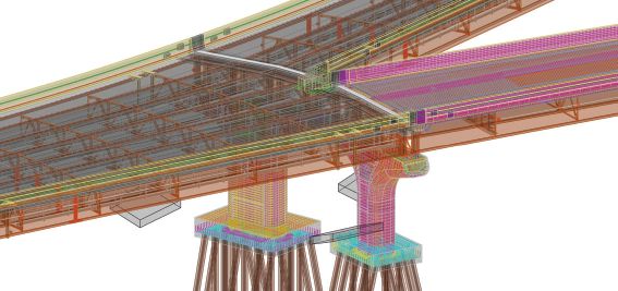
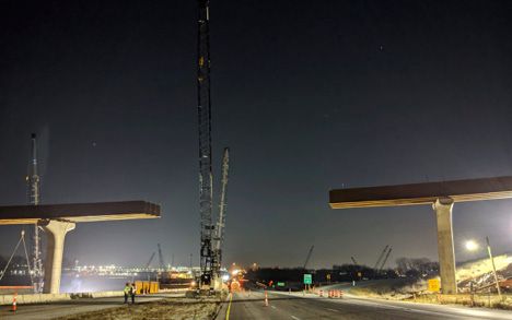
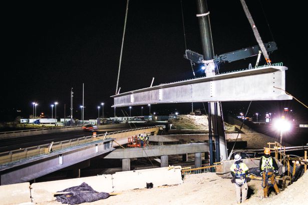
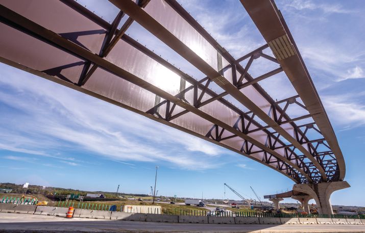
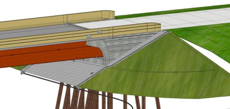
A BIM (top) of I-80 flyover bifurcation before IowaDOT began construction (bottom).

A Push from the Top
BIM not PDF
As most in the industry know, digital design and 3D modeling have been parts of the normal design-to-construction workflow for many years. Unfortunately for the industry’s overall efficiency, the normal workflow also includes 2D drawings, usually shared as PDF files, serving as the legal documents submitted for review, contracting and construction. The result is the potential for design intent to be lost when converting from 3D models to 2D plan sheets or, more commonly, less design detail being generated in the first place.
Both scenarios leave gaps in the overall intent, opening the possibility for requests for information, change orders, schedule delays and possible legal conflicts. It also results in an incomplete as-built model, inhibiting efficient facility management during the life of the asset. To usher in broad acceptance of BIMs as legal construction documents and as an alternative to 2D PDFs, a standard workflow and data exchange model is needed that satisfies the requirements of designers, reviewers and contractors.
A Roadmap
In a pair of 2013 papers, “Bridge Data File Protocols for Interoperability and Life Cycle Management: Information Delivery Manual for Highway Bridge Interoperable Data Protocols” and “Bridge Data File Protocols for Interoperability and Life Cycle Management: Model View Definitions for Highway Bridge Interoperable Data Protocols,” S.S. Chen et al identified the shortcomings of existing BIM data schemas and workflows for use on bridge projects, and mapped a path forward for using BIM for bridges and structures. Their recommendations included extending the existing Industry Foundation Classes (IFC) data schema to support items specific to horizontal design and construction, such as roadway horizontal alignments, vertical profiles and cross sections. IFC data schemas are developed and maintained by buildingSmart International (bSI) with broad support from the international community.
In 2016, the USDOT Federal Highway Administration (FHWA) prepared a report, “Bridge Information Modeling Standardization.” Volume 1 of the report was intended to identify an existing information sharing model (i.e., “schema”) that would facilitate the exchange of information in bridge design plans as they go out for bid. The authors reviewed schemas including IFC, which already is supported by major software vendors in the building industry; LandXML, which is supported by major software vendors for infrastructure; and OpenBrIM, an FHWA-supported “Bridge Information Modeling” format.
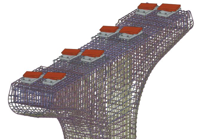


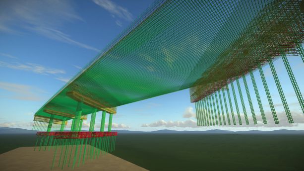
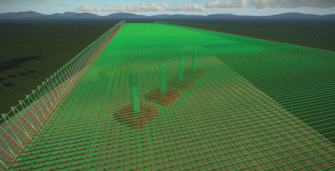
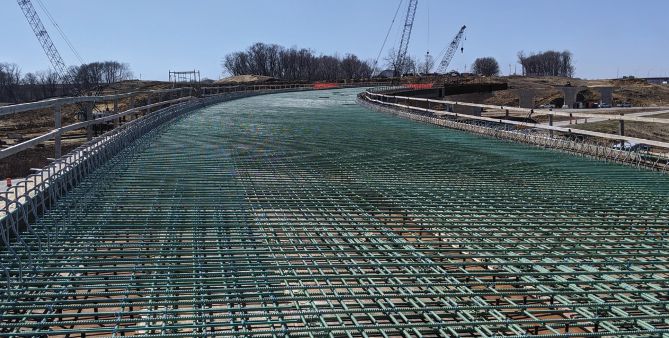
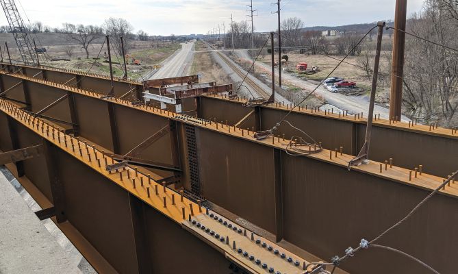
Images (from top to bottom) show the IowaDOT pier reinforcement BIM, contractors prepping rebar, and the completed pier with steel.
Like Chen a few years earlier, the researchers concluded the most suitable schema is IFC, with some extensions to the current version required to cover critical gaps in data type support. This decision was based on a number of factors, including already-defined support for most required bridge data types, wide existing vendor implementations, broad international community support and that the schema is an enforceable ISO standard.
In 2016, the Technical Committee on Technology and Software (referred to as T-19) initiated a study funded by the National Cooperative Highway Research Program (NCHRP, the research arm of the American Association of State Highway and Transportation Officials (AASHTO)). The project, “Standardized Format for Bridge and Structure Information Models,” presented a framework for BIM implementation and provided T-19 a list of actionable items, including the following:
• The decision to develop a Model View Definition (MVD) compliant with IFC data models (software vendors implement MVDs in their design applications to enable reliable exchange of IFC data models).
• That the initiative to move BIM for Bridges and Structures into standard practice would require more effort than T-19 members could handle themselves, so use of a consultant/contractor would be necessary.
• Deciding on two sources of funding: the FHWA and an AASHTO Transportation Pooled Fund Study (TPFS).
A Group Effort
In 2017, working from the T-19 recommendations and citing the desire “to take advantage of the efficiencies associated with the use of BIM in transportation structures,” AASHTO launched a five-year program Transportation Pooled Fund Study (TPF-5(372)), “Building Information Modeling (BIM) for Bridges and Structures,” led by the Iowa Department of Transportation with support from HDR, an AEC consulting firm.
The defined scope of work for the pooled fund study includes the following:
• Establish standards to facilitate the wide use of IFC as an exchange standard in BIM for Bridges and Structures in bridge projects.
• Develop the national standard MVD.
• Collaborate with buildingSMART and software vendors to offer BIM for Bridges and Structures training.
• Conduct return on investment (ROI) analysis to quantify the benefits of using BIM for Bridges and Structures.
• Develop a contract template for BIM for Bridges and Structures projects used to conduct risk evaluations for deploying BIM for Bridges and Structures.
• Provide recommendations and project management services to T-19 in relation to the development and implementation of BIM for Bridges and Structures.
• Establish a forum/expert hub for practitioners to promote the common modeling formats and share experiences.
• Provide technical support, organize training workshops, and facilitate pilot/demonstration projects for bridge owners to encourage and accelerate the adoption of BIM for Bridges and Structures.
With a recommended data schema selected as well as the support of AASHTO and the FHWA, the pooled fund has attracted more than 21 state DOTs, each committing funds to support the goals and scope of the project and eager to initiate pilot projects to vet the concept.
Defining a Practical Standard
A main factor in gaining traction with the design, review and construct ecosystem is the development and use of software that complies with the schema outlined by Chen, the T-19 project report, and scoped by the pooled fund. Although BIM for Bridges and Structures projects can and are proceeding without such capable software, wide adoption will require out-of-the box compatibility with future infrastructure IFC schemas and ease-of-use functionality that aren’t yet available on the market.
Responding to an RFP from the TPF-5(372) committee, HDR and others are building on work previously completed by the international community to develop MVDs to transfer all required information from the bridge designer to the contractor to facilitate model construction. In March 2019, bridge-specific types and entities for the IFC Bridge extension and Model View Definitions for bridges were added to IFC Bridge Candidate Standard 4.2 (bit.ly/3cnjSqf). This is the first version to include items for infrastructure, and it’s currently under review by the international community. If approved by the bSI, these MVDs then must be incorporated into and supported by software available in the general market and eventually used by design engineers, contractors and other service providers. The software then would be certified as compliant in support of TPF-5(372) MVDs.
To encourage software vendor engagement and participation, the TPF-5(372) committee released in November 2019 the “Software Vendor Engagement Plan,” its five-year plan documenting the components and timetables necessary to engage vendors to create software solutions to support BIM for Bridges and Structures as defined by the committee. A number of software vendors and members of bSI expressed interest in the program, including Autodesk, Bentley Systems, Nemetchek and Trimble. Further, the OpenDesign Alliance created and maintains a toolkit for IFC interoperability, which its members can license to develop compliant software.
Design, Review and Construct
While HDR continues to work with AASHTO and bSI on the schema and software standardization, state DOTs are vetting 3D digital delivery methods and workflows on pilot projects. Currently, more than 20 pilot projects in more than a dozen states are in various stages of design, review and construction.
“It’s no coincidence that every one of [the pilot projects] is being done by a member of the pooled fund,” says Connor Christian, EIT, transportation BIM program manager with HDR, who works closely with members of the pooled fund study. The results thus far are promising. The goals of each pilot vary from state to state and project to project.
One of the first pilot projects is owned by the Utah DOT (UDOT) and includes three structure replacements on Interstate 80 over existing Union Pacific tracks. An emphasis was put on using the 3D models as the record deliverable, and the design was created and delivered to the contractor using only 3D model formats.
UDOT also piloted 3D deliverables on the 5600 West Railroad Crossing project, with improvements including widening the roadway and adding additional lanes of traffic in both directions. This project also includes building a new bridge over the Union Pacific Railroad tracks. The engineer on the project is Michael Baker International, with support from HW Lochner.
Yet another pilot project is underway in Iowa, engineered by HDR. The Iowa DOT I-80/I-380 Systems Interchange project located west of Iowa City, Iowa, is a comprehensive redesign of the interchange and includes ramp-bridge replacement as the first phase of interchange reconstruction. The ramp bridges consist of a five-span diverging gore followed by a 13-span curved ramp carrying the northbound movement and a three-span curved ramp carrying the southbound movement. These complex curved steel plate-girder ramps were chosen to investigate the use of BIM in design and construction. The project goals were to develop a “complete as possible” BIM of the bridges, evaluate the BIM software and assess the model use during construction.
Legal Digital Models
Before any design or review of the pilots could proceed, the issue of signing and sealing the design has to be addressed. For a typical project, the 2D plans signed and sealed by the design engineer are the legal documents and are part of the construction contract. 3D digital delivery invites the question: How does one sign and seal a 3D model?
The states exploring 3D delivery have taken varying approaches to answering this question. Utah accepts a signed and sealed physical list of the models that are part of the contract documents. New York statutes state all “plans” must be signed and sealed by the engineer. To accommodate 3D models, the state redefined “plans” to include 3D digital models.
From Design to Construction
The design, review and construction workflows on projects utilizing 3D digital deliverables vary in a number of ways from those used on projects with traditional deliverables. These include differences in design development; the methods and tools used to review the designs; and the processes contractors use to extract information from the models, request information and resolve discrepancies.
Design
According to Alexa Mitchell, P.E., Highways and Roads BIM director with HDR, “there is a significant change when designing for 2D sheets, compared to developing a 3D model and BIM. For example, when designing in 2D, road cross-sections only show every 50 feet [along the alignment]. However, a 3D model must show details for the entire length of the alignment.”
This added detail results in a more-complete conveyance of the engineer’s design intent and “alters the way you design,” says Mitchell. Owners are recommended to allow for a 10 percent contingency in the contract to account for added engineering, modeling and ongoing support efforts and to work with the engineer to identify efficiencies to offset any additional costs.
Prior to developing the BIM, engineers at HDR worked with Iowa DOT to develop a BIM execution plan that defines the level of detail (LOD) required for the BIM, asking “what is the purpose of the model?” Similarly, working with UDOT, HDR developed a BIM execution planning process to coordinate work on the project. This led to creation of a standardized BIM planning process for UDOT use on future projects. The project concluded with a review and rewrite of the UDOT Structure Design and Detail Manual to account for lessons learned during the pilot project.
The BIM for the bridges was created exclusively with Bentley software. The software was evaluated for ease of use, development capabilities, parametric capabilities, and information storage and display.
Review
Digital models provide several benefits and also create challenges for reviewing agencies. During these early pilot projects, as the workflows are being developed, a hybrid approach to review is sometimes warranted.
For example, on the Iowa DOT I-80/I-380 project, design engineer HDR provided complete, traditional, unapproved 2D design plans that were eventually turned into a BIM deliverable. Initial review and commenting was done traditionally. Then, according to Ahmad Abu-Hawash, P.E., chief structural engineer with the Iowa DOT Bridges and Structures Bureau, the BIM model “was reviewed by doing many dimension and elevation checks. For plate size checks, etc., we used Bentley Navigator software.” The ability to comment directly on the model was limited by problems related to resolution with the Navigator. “We had questions about using the software and getting the information out of it,” explains Abu-Hawash.
At UDOT, Project Manager John Montoya and his colleagues used Bluebeam Revu on their pilot projects to review and provide comments. “Due to our relative inexperience with the software tools, complication [in reviewing] came from the DOT, not the design.” Internal challenges also included making sure staff had access to the computer hardware needed to review the models.
Other challenges include preparing quantity takeoffs for budgeting and contractual use. At Iowa DOT, quantity take-offs were performed using both the model and traditional means. However, hinting at future model benefits, a bill of bar schedule was generated directly from the model. The reviewer then independently verified bar details by developing all necessary sections in a separate 2D CAD file.
Construct
To encourage use of the BIM files during construction, select models were used as the signed and sealed bid document for the project. The model files for the pilots are shared via various web-based tools, including Projectwise, DocExpress and e-Builder. As with the project’s design and review stages, construction from 3D models creates its own set of challenges, including extracting dimensions and quantities from the model; viewing the model in the field; submitting requests for information; and coordinating with subcontractors.
Although the design engineer and state DOTs typically have software fully capable of viewing and working with the models, this isn’t always the case with contractors. Thus, some state DOTs, such as UDOT, made available to contractors “light” versions of Bentley software. Joe Jenson, project manager with general contractor Wadsworth Bros. Const. Co. Inc. for the UDOT 5600 West Railroad Crossing project, explains that although some general contractors have in-house software and technical expertise, their subcontractors often need more support. “It’s a learning curve, and we’ll all eventually get there.”
To help with some of the challenges related to working with the model, the design engineers are contracted to remain engaged throughout project construction. As such, they’re able to assist in quantity takeoffs, creating model views, extracting dimensions, and providing general technical support to those accessing the model.
Working with 3D models instead of 2D plans presents additional changes to requests for information (RFI) workflows. In both Utah and Iowa, RFIs are submitted in the traditional way, either via email or e-Builder. Responses that result in changes to the design are shared as sketches or smaller 3D models. Eventually, the revisions are incorporated into the complete 3D project model, which then is republished and shared with the entire team.
Challenges notwithstanding, UDOT’s Montoya is focused on the benefits. “We were happy with how the bids came in,” he notes. “The very competitive bidding indicates contractors are adapting to these 3D models.”
Jenson echoes the enthusiasm, “I like it, I think it’s a good thing. There are glitches, but they will get worked out.”
And Iowa DOT’s Abu-Hawash summed it up by adding, “we knew we’d have issues. We must try [3D model delivery] to know what works and what doesn’t.”
Benefits, Challenges and Future Opportunities
Even while acknowledging hurdles, challenges and hiccups, everyone interviewed for this article expressed positive experiences using 3D models as plans for construction. Although engineers and designers have the most experience working with 3D models and modeling software, there are still workflow issues that require attention, including a better understanding of what’s needed to transition from 2D PDFs to 3D models.
“Not everything in the model has to be in 3D,” says Mitchell. “BIM is also about information along with 3D models. [Everyone involved] needs the ability to read metadata from 2D and 3D geometry.”
Others expressed similar thoughts, including Iowa DOT’s Abu-Hawash. “The majority of bridge contractors are not familiar with BIM and do not have the experience with extracting information from the model,” he notes.
Jenson with Wadsworth agrees, “The main challenges are the ability to view the model and getting people onboard with 3D instead of 2D.” However, all are optimistic about the future of BIM for Bridges and Structures. “It is a matter of time before contractors gain experience,” says Abu-Hawash.
The refrain about the lack of comprehensive tools for viewing and working with the models in the field was repeated nearly universally, as was the belief that, in time, this issue would be addressed by software vendors as they implement MDVs based on IFC schemas. “Software developers and vendors have been very supportive of this initiative,” adds Abu-Hawash.
As the workflows, viewing and editing software, and the models themselves improve, pilot project members see positive outlooks, including reduced change orders (and the costs and time delays frequently associated with them); faster project delivery; improved safety; and reduction in construction cost and claims.
“More accurate models will facilitate better control of work in the field,” says UDOT’s Montoya. “The ability to compare the delta between the model and what is actually happening in the field will help us stay on top of materials and quantities.”
The ability to detect and address conflicts during design is another example of the benefits, especially as the models begin to incorporate other disciplines such as geotechnical, roadway, drainage, utilities, lighting and so on, which will improve constructability. Another major benefit is the use of the models in asset management. Future models will be continually updated throughout the lifecycle of the structure, from inception during preliminary design and concepting, through in-service inspections and eventually decommissioning.
As Christian states, “Change is happening now in the industry. It’s not coming, it’s here. When will everyone join?”

Mark Scacco
Mark Scacco, P.E., is a 25-year veteran of AEC technology and design consulting. He is an AEC Industry Consultant with Scacco LLC and can be reached via email at [email protected].
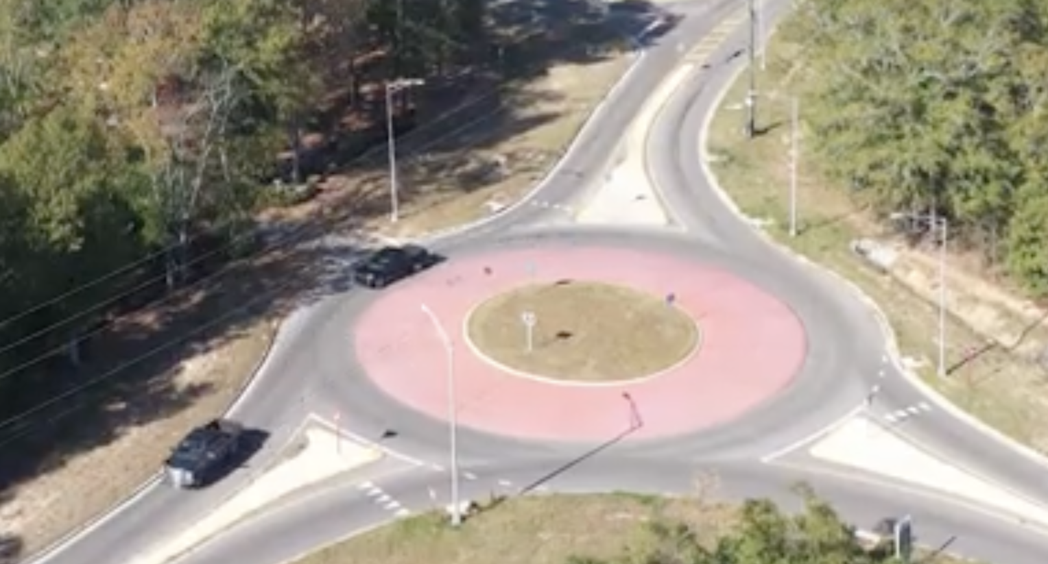
Video: New Roundabout Under Construction at McIver and Old Florence Roads in Darlington County
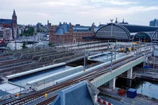
Bridge Replacement at Amsterdam Centraal Station
June Issue 2026
.jpg?width=225)