By Gregory P. Taravella, P.E., and James W.H. Costigan, E.I.
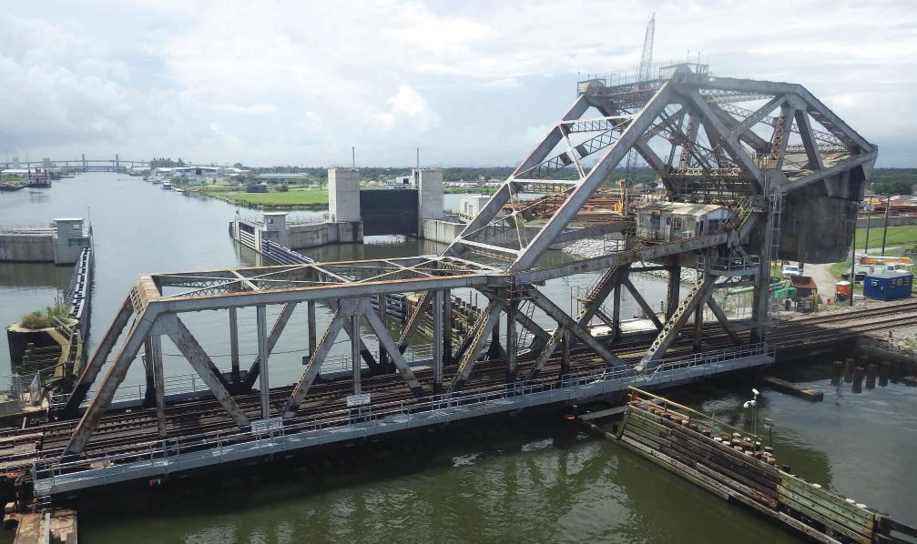
The Seabrook Bridge is a Strauss Heel-Trunnion Bascule Bridge located in New Orleans and owned by the Port of New Orleans. Built in 1923, the through-truss bridge originally carried two railroad tracks inside the trusses and two single-lane roadways cantilevered outside the trusses. The bridge is one of three duplicate bridges that cross the Inner Harbor-Navigation Canal (IH-NC), which links the Mississippi River to Lake Pontchartrain.
The Seabrook Bridge crosses the canal adjacent to Lake Pontchartrain and is subject to frequent lake inundations of brackish water. During the last 95 years, the original paint coating deteriorated, which resulted in severe corrosion of the existing metalwork within the splash zone, including the railroad and highway floor systems and bottom chord elements. Deterioration of the highway floor system components prevented traffic from using the bridge, and the roadways were closed. To maintain the bridge’s future capacity to continue to carry railroad loads, significant remediation of deteriorated splash zone components was required.
Remediation of these bridge components began with the removal of the existing cantilevered roadways comprised of floorbeams, stringers, bottom laterals and decking during an emergency project in 2014 to keep these components from falling into the channel and becoming a navigation hazard. During this removal project, the balance condition of the bridge had to be maintained throughout construction as the cantilevered roadways were removed. Six panels of ballast beams were added outboard and inboard of each truss, beginning at the bascule toe, to counter removal of the cantilevered roadways.
Following the 2014 roadway removal project, the existing railroad floor system and bascule truss bottom chords remained in severe condition and warranted complete replacement. The subsequent project included replacement of the entire railroad floor system comprised of floorbeams, stringers, truss bottom laterals, and truss bottom chords from the toe end of the bascule span to the end of the tower span. Elements of existing bottom chords juxtaposed about the main trunnions had upper compression elements strengthened and lower corroded tension elements replaced. This project was developed during the first 10 months of 2016; construction began in November 2016 and was completed in December 2017.
Bridge Owner: The Port of New Orleans
Railroad Owner: Norfolk Southern Corporation
Key Stakeholder: U.S. Coast Guard
Engineer of Record: Modjeski and Masters
Floor System and Bottom Chord Contractor: Complete Engineering Construction, Inc.
Mechanical Replacement Contractor: Scott Bridge Company
Design Project
The bridge’s double-track rail traffic is operated by the Norfolk Southern Corp., and approximately 15 trains per day cross the span on inbound and outbound tracks, including a northbound and southbound Amtrak. Stakeholders included the Port of New Orleans, several boat builders who have businesses located just south of the bridge on the IH-NC, Norfolk Southern and the U.S. Coast Guard.
In the early stages of the design phase, and after several meetings with stakeholders, a construction matrix was developed to describe five viable construction alternates. The construction alternates listed construction time, railroad and marine closure durations, estimated construction cost, and advantages and disadvantages. Each construction alternate included three months for shop-drawing review and fabrication as well as two months for mobilization and demobilization.
“Construction Alternate B” was deemed favorable to the project due to its estimated 12-month construction time, cost of approximately $6 million and the 16 weeks of three-day marine and rail closures required for the floor system and bottom chord changeout.
The construction matrix was further refined to incorporate agreements brokered by the Port of New Orleans with the Norfolk Southern Railroad and the U.S. Coast Guard that changed the closures from 16 three-day closure weeks to 14 four-day closure weeks that coincided with 86-hour continuous marine closures. Transition to a four-day closure week and detailed step-by-step construction sequences for each major work item provided confidence to the stakeholders that one panelized floor system and bottom chord panel could be replaced within one four-day closure week. This enabled further refinement of the 14 closure weeks to 10 closure weeks required for the floor system and bottom chord replacements, two closure weeks required for bottom chord strengthenings and partial replacements, and two closure weeks required for bearing replacements.
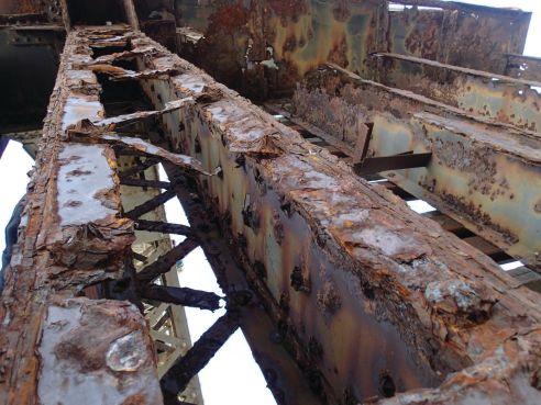
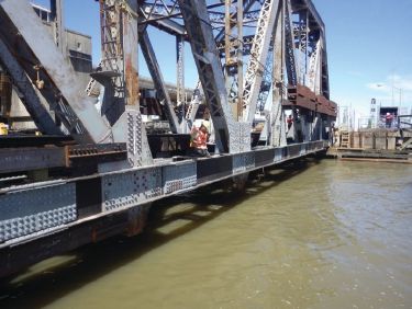
A photo shows a deteriorated truss bottom chord member of the Seabrook Bridge.
The existing built-up riveted floorbeams and rolled I-beam stringers were replaced with built-up welded floorbeams and rolled I-beam stringers heavier than the weight of the elements removed. This was done to remove half of the ballast beams that were added during the 2014 emergency roadway removal project. All replacement material was ASTM A709 Grade 50 that was shop primed with a zinc primer and field coated with two coats of coal tar epoxy. Existing and replacement stringer spans were spliced to accommodate transitions from existing elements to replacement elements between closure weeks.
Existing built-up riveted bottom chords, comprised of web plates, angles and double lacing, were replaced with two types of chords. At panels with low dead load, located at the first bascule span panel and the rear tower panel, in-kind chord replacements were designed comprising of inward-facing built-up welded channels and stay plates. All other bascule bottom chord replacements were comprised of welded outward-facing built-up channels. These chords were spliced near each truss panel point to panelize the work.
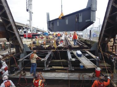
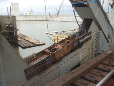
A photo shows the new floorbeams and stringers being placed into the bridge.
With this panel replacement strategy, one chord panel along with one floor system panel could be changed out per closure week. These replacement chords were stood-off the existing gusset plates by 3 inches with steel plates, so the back of replacement chord webs would clear the rivet heads on two existing chord splices located along the existing chord. All replacement floorbeams and bottom chords were attached to truss gussets using temporary ASTM F3125 Grade A325 bolts followed by permanent ASTM F3125 Grade A490 bolts. For replacement bottom chords, this was done after existing chords were removed.
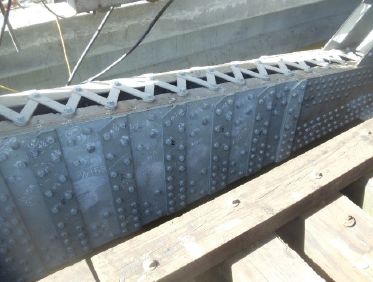
Photos show the bridge’s new bottom chord outward-facing channels (top) as well as the bottom chord web replacement splices (bottom).
A chord jacking assembly was needed for the repairs.
Existing bottom chords about the main trunnions were strengthened. On the bascule side of the main trunnion, the 14-foot-long chord consists of a top compression box comprised of web plates, four angles and double lacing as well as a bottom tension strut comprised of side plates and two angles. The top box was strengthened by adding four angles, one in each corner of the box spliced at midspan. These new angles were the same length as the compression member and required fill plates as the angles were attached to the truss gusset plates. This box required one-half of the dead load compression of 425 kips be removed from the member so one-half of the top and bottom double lacing could be removed for painting access without reaching the member’s critical buckling stress. The bottom strut was replaced in-kind, one-half at a time.
On the tower side of the main trunnion, the 21-foot-long chord consists of a top compression element comprised of a continuous web and side plates, two angles and single lacing, and a bottom tension box comprised of web and side plates, four angles and double lacing. Existing 8-foot-long web plates between splices exhibited long corrosion holes and were replaced. The compression capacity of the existing box allowed no more than 2 feet of existing web and two panels of lacing be removed at one time. Installation of four web splices over the 8-foot web replacement zone required a repair sequence. This existing chord also required one-half of the dead load compression to be removed. After the continuous web was replaced, the bottom tension box was replaced in-kind, one-half at a time.
This type of bascule bridge under dead load is affected by the 2-million-pound counterweight and required jacking procedures to transfer compression load out of existing chord members for replacement. The counterweight pulls the bascule span toward the main trunnions, placing the bottom chord in compression and the top chord in tension. To take advantage of this, a separate sequence was developed to have dead load, live load and impact load in the replacement bottom chords. This sequence began with installation of replacement bottom chords on ASTM F3125 Grade A325 temporary bolts, followed by installing jacks and jacking struts centered about the existing bottom chord above and below the chord, followed by loosening nuts on the temporary bolts, then jacking the dead load out of the existing chord, removing the existing chord, and replacing temporary bolts with permanent ASTM F3125 Grade A490 bolts one at a time. Lastly, the jack pressure was relieved to place the loads on the new chord.
During the pre-bid process, the contract required the contractor to have 50 percent of fabricated material onsite prior to the first closure week. Also, Norfolk Southern Railroad agreed to operate on one track, which meant the contractor would only need one track in service by the end of each closure period. This requirement and concession provided the stakeholders greater confidence that the contractor would be able to complete the contract within the time allotted.
The contract was awarded to Complete Engineering & Construction Co. based out of Lafayette, La., the sole bidder at $6.7 million, and the “Notice to Proceed” was issued to the contractor on Nov. 4, 2016. The first closure week would begin on Jan. 9, 2017. This meant the contractor had to develop shop drawings, obtain the engineer’s approval of the shop drawings, fabricate a least 50 percent of the material, and ship it to the site before Jan. 9, 2017. This goal was met by the contractor developing the shop drawings based on as-built shop drawings that were field verified, and by taking field measurements at the site. Most replacement floorbeams, stringers, and bottom chord shop drawings were approved by the end of November 2016, and fabrication of these elements was completed by the end of December 2016. During this time, the contractor also replaced thousands of rivets with ASTM F3125 Grade A325 temporary bolts.
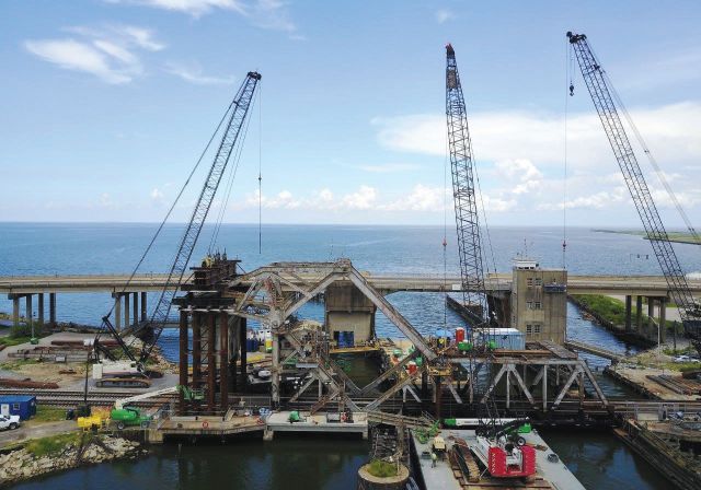
Two separate projects commence work on the Seabrook Bridge simultaneously.
Construction
During the first three 12-hour days of a typical four-day closure week, the contractor replaced rivets with temporary bolts, installed stringer splices on four existing stringers, installed a replacement outboard bottom chord and standoff plates, removed a portion of existing floorbeam web and connection angles, installed the inboard replacement chord and standoff plates, and converted continuous rail of the live track to jointed rail. All this work was completed prior to the fourth day: the floor system changeout day.
There were 12 four-day closure weeks allotted for floor system replacement as well as bottom chord replacement and strengthening. The first floor system replacement, the end floorbeam and stringer stubs located at the toe of the bascule span, took 10.5 hours. The final floor system replacement, located in the tower span, lasted only nine hours. Existing bottom chord replacements and strengthenings were performed at both trusses during a closure week.
Two closure weeks also were designated for replacement of pier bearings and grillages located at the bascule toe at the rest pier. Previously, the railroad used shims under timber bridge ties to make up for the loss in the bridge bearing depth due to corrosion of the bearing plate. This corrosion caused a poor bearing condition for the bascule span, unacceptable span lock clearances and rail signal issues. These issues were solved during the design phase in which corroded bearing and sole plate metalwork were designated to be replaced with a stainless-steel sole plate as well as connection angles and shims. A thicker sole plate was provided so shims would no longer be required at the timber bridge ties at this joint location and for span lock alignment.
The contractor was required to survey this joint location from top to bottom to determine the required shim thickness to align the bascule rails with the approach rails and the span lock with the span lock receiver stand. This required the contractor to finalize this joint geometry after the pier grillages were replaced, and the bearing and receiver assemblies located atop each grillage were cleaned, repainted and reinstalled. Replacement grillages were encased in two 13-inch lifts of high-strength grout, and new anchor bolts were stainless steel. Upon completion, the bascule span had an acceptable bearing condition, the span locks had acceptable clearances, and the rail had consistent signal.
The floor system and bottom chord replacement work were completed on April 16, 2017, and the contractor had until the end of 2017 to complete other work items, including adding access outside both trusses, construction of a parking platform for the operators, replacing bascule navigation lighting and making final balance adjustments to the bascule span and counterweight.
In December 2016, a damaged component of the mechanical system ceased operations of the bascule span for safety reasons. This ultimately led to an additional multimillion-dollar project within the subject project timeframe. Further coordination effort was required for the subject project due to an additional contractor onsite. Fortunately, the balance condition of the structure during the floor system changeouts was waived as the bridge was locked in the lowered position. Instead of performing balance checks after each closure week, the contractor was only required to perform an initial, intermediate and final balance check.
Conclusion
The work included a high level of partnering that took place between the owner, railroad, design engineers and contractor’s engineers combined with timely meetings, collaborations and field visits held to head off potential issues. This approach proved to be highly advantageous and is one of the reasons behind the project’s success. From the time design began through to the end of construction, the effort expended by all involved to provide a robust replacement culminated in giving the Port of New Orleans a retrofitted bridge that could now carry current rail traffic for the next 100 years.
Gregory P. Taravella has been working for Modjeski and Masters for more than 38 years and is currently a supervisor engineer of structures in their New Orleans office. Jim Costigan is a field engineer with the Modjeski and Masters New Orleans Office; email: [email protected] and [email protected], respectively.

Gregory Taravella
Gregory P. Taravella has been working for Modjeski and Masters for more than 38 years and is currently a supervisor engineer of structures in their New Orleans office. Jim Costigan is a field engineer with the Modjeski and Masters New Orleans Office; email: [email protected] and [email protected], respectively.
Video: New Roundabout Under Construction at McIver and Old Florence Roads in Darlington County

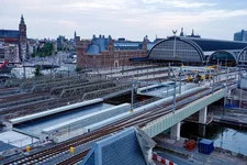
Bridge Replacement at Amsterdam Centraal Station
June Issue 2026
.jpg?width=225)