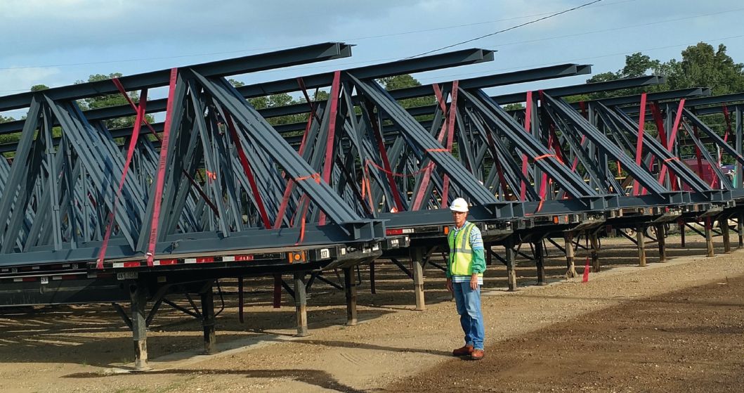
The flat roll steel mill being constructed in Sinton, Texas, is the largest ever undertaken by steelmaker Steel Dynamics Inc. The $1.9 billion, 1,000-acre campus includes coating lines, cold and hot mills, and a melt shop that features a state-of-the-art electric-arc furnace with 24-foot-diameter exhaust ducts. Nearly 500 joist girders were specified by CSD Structural Engineers, the engineer of record (EOR) for the project. But the largest and heaviest of these joist girders posed exceptional engineering challenges for the supplier, New Millennium Building Systems.
The engineering of the giant joist girders, a collaborative and dynamic process, was still underway at the time this article went to press. As George Batcha, CSD’s vice president reports, “It’s important as we are laying out the overall building to discuss the joist girder geometry and loads with New Millennium, so we can develop a system that is straightforward to build and ship. On this project, there are unique large-loading requirements that make this even more important.”
What About JG-321?
JG-321 is one of the largest roof joist girders being fabricated for the project. Located in the melt shop, the joist girder was originally specified to be 136-feet, 6-inches long, which would have been a shipping concern. JG-321 also was specified to include a top chord extending 8 feet, 6 inches beyond the load-bearing perimeter wall to support two roof joists and wall girt loads outside. In addition to the joist girder’s added length, the top chord extension would need to support large loads, adding to material cost. JG-321 needed to be rethought.
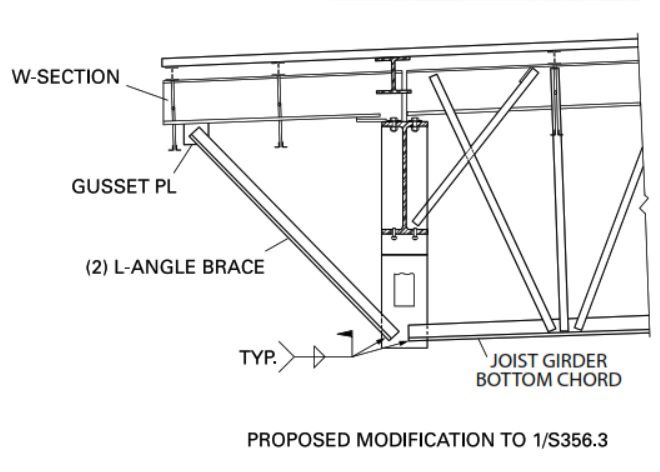
“We worked with George Batcha at CSD to devise a way to shorten the girder without extending the top chord,” explains New Millennium’s Lloyd Smith. “A W-section beam serves as a propped cantilever to support the two roof joists and wall girt loads. A double-angle kicker brace supports the beam segment. This created a torsion problem for the girder support beam, so we stiffened the girder by designing it for a fixed-end moment that resolves all the forces and resists the beam torsion. The final solution allows us to fabricate and paint the joist girder, then ship it in one 128-foot-long piece.” (See Figure 3.)
Confronting Two Monsters
Among the nearly 500 joist girders specified for the project, JG-325A and JG-325B have been referred to as “the two monsters” by Lloyd Smith. Also located in the melt shop building, these are the two heaviest roof joist girders on the project. Their chord forces due to the loading involved defied the notion that these two might somehow be shipped in halves and field-bolted together onsite. The sheer size of the required splicing plates, W-sections, bolts and welds raised the possibility of it all not fitting the joist girder panels.
Given the large forces involved, a more-efficient approach was needed. Some of the early ideas discussed by New Millennium and George Batcha were quickly taken off the table. The EOR confirmed that the roof joist girders couldn’t be doubled up to reduce load, even though the column cap plates were large enough. The melt shop’s building design had been completed, and the structural steel detailing and fabrication were underway.
Joist girder deflection was a concern in addition to stress. Deflection could be relaxed if counteracted by camber, but this had to be evaluated by the design team. Although it was acceptable to the EOR to use joist girder chord material having higher-grade steel—ASTM A572 Grade 55 (Fy = 55 ksi) or ASTM A572 grade 60 (Fy = 60 ksi)—the benefit proved inadequate. Higher steel strength didn’t reduce the chord sizes as much as needed, and increasing steel strength doesn’t improve stiffness. Also, the higher-strength steel would’ve had to be purchased in larger amounts than needed for the project.
As is often the case on larger and more-complex engineering projects, a new solution to the two monsters emerged. New Millennium developed a plan to fabricate and ship the two joist girders, each as one piece, without splicing. Based on further design coordination with the company’s sister fabrication plant in Juarez, Mexico, it was determined that the sister plant would supply the two girders.
Uplift in Hurricane Alley
Along with its access to nearby Corpus Christi, Texas, and gulf shipping lanes, the new flat roll steel mill complex will be exposed to the perennial risk of hurricanes.
Often in the region, a diaphragm and shear wall system is specified to resolve lateral wind forces into the foundation, but the majority of the new mill complex doesn’t employ diaphragm and shear walls. The lateral-resisting system for each structure is a braced-frame and fixed-base-column system. The walls resist the wind with girts made from open web steel joists. These are hung with sag angle from the roof joist and joist girder structure.
Wind forces are resisted and transferred to the wind columns by the girts, and the wind column forces transfer to the roof joists. The joist and joist girder seats transfer the forces into the chords and back through the seats at the other end, then into fixed-base columns or braced frames down to the concrete foundation. The collector roof joist top chords are only braced by the joist bridging system, and the girder top chords are laterally braced by the roof joists. (See Figure 4.)
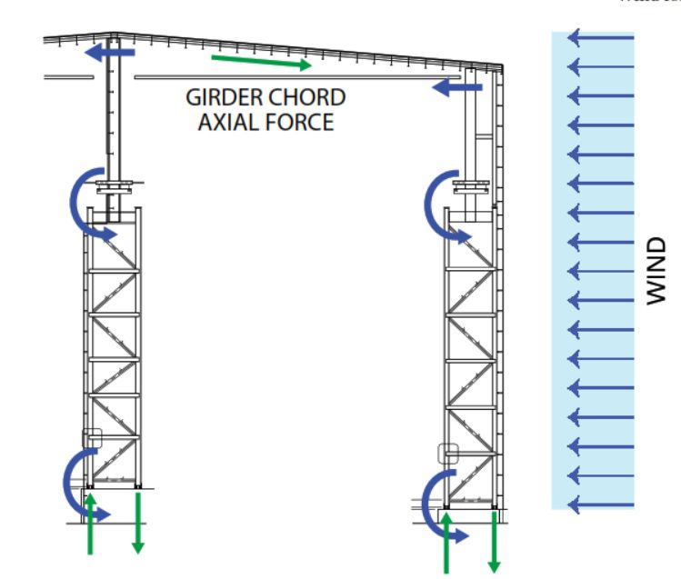
in the new flat roll mill complex require framed members to resist, transfer and resolve all wind loads.
“The large collector axial forces are significant for chords that are not continuously braced,” says Smith. “Some axial forces are so large that we couldn’t take them through the joist seats, and we had to coordinate strap plates to transfer the forces to the next joist, and the next, and so on, before eventually resolving them into the structural frame.”
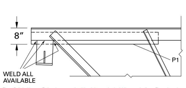
At the perimeter, the force path involves rollover to the joist girder seats, so stiffener plates are required at those seats. Smith says strap plates can’t be used for the joist girder seats at the fixed-base column towers, so the joist girder top chord axial forces need to transfer through the seats. This requires significant reinforcing material at the joist girder end panels, with large chords in a sloped seat situation.
“The sloped seats are made as a drop below the reinforced chord double stem T-plate,” adds Smith. “Large moment forces on weld groups had to be analyzed and designed in conjunction with high uplift reactions.” (See Figure 5.)
Crane Clearance
For two of the bays within the new flat roll steel production campus, crane clearance is another engineering challenge related to the big roof joist girders. To support the required structural loads in the scrap bay, two already massive 96-inch-deep joist girders each need to be increased by 1 foot to 108-inch depth; and in the caster/tundish bay, three joist girders would need to be increased from a 96-inch depth to 120 inches to support the loads there.
The EOR confirmed these increases wouldn’t cause any interference with overhead crane clearance, but other possible issues can come into play. The building owner was consulted for possible related concerns, such as duct clearances, maintenance platforms, conveyor systems, etc.; and the fabricator was consulted regarding possible detailing and fabrication considerations. All matters were discussed and resolved.
The immense Steel Dynamics mill complex is still rising up from CSD’s structural drawings. As CSD’s George Batcha observes, many of the giant joist girders specified for the project will require detailed design collaboration to further address specific design challenges, with possible modifications to structural steel details.
“That high level of collaboration is essential,” says Batcha. “It assures the most economical solutions, while meeting project and building code requirements.”

John Barnett
John Barnett is a journalist reporting on steel building design and construction; email: [email protected].
Video: New Roundabout Under Construction at McIver and Old Florence Roads in Darlington County

Promenade at The Point

June Issue 2026
.jpg?width=225)