Publisher’s Note: I met structural engineer Clark Baurer when I served as a juror for the Structural Engineers Association of Illinois’ (SEAOI) Excellence in Structural Engineering Awards Competition—his elegant and innovative structural renovation of Chicago’s Theater on the Lake won the Lavicka Award for Small Firm/Small Project up to $2 million. The project hit a sweet spot for me: repurposing an old structure as well as a complicated structural challenge. Clark’s use of hand drawings was an added and interesting bonus, and his creativity and engineering acumen turned a shuttered historical building into a new gem on the Chicago shoreline.
— Kevin Carmody
For one thing, research suggests that up to 75 percent of the population strongly uses visual thinking—or both visual/spatial thinking and thinking in the form of words—when problem solving … and surely the percentage is somewhat higher in the design professions. Drawing by hand is more than a useful or quaint skill for visual thinkers; it’s more like a brain-augmenting superpower.
Drawing (and thinking) by hand slows down the design process at the very phase when moving slowly is most useful and, perhaps paradoxically, most efficient. Mistakes or wrong assumptions that may be missed or glossed over when working quickly with digital tools are not usually missed when proceeding thoughtfully, sketching and making notes with pencil (and eraser) in hand.
According to Stewart Brand in his book, How Buildings Learn: “Work done in haste is necessarily shoddy, a house of cards. On a go-fast schedule, there is no margin for a single error, and error is inevitable. High risk, high loss. The opposite strategy is much surer, because the errors are piecemeal and correctable. When you proceed deliberately, mistakes don’t cascade, they instruct. Low risk plus time equals high gain.”
I have found that working out solutions by hand allows inspiration to visit. Artists and writers know this: great books, music and art are nearly always preceded by rough sketches in a journal or the lovely phrase or compelling idea jotted down on some handy scrap of paper. The public doesn’t think of our profession as one that requires creativity, but we engineers know better: the best work is based on the best ideas, and the best ideas are inspired, not looked up in a technical manual or calculated in a spreadsheet.
Perhaps I can support this call for more sketching and drawing by hand by describing my work on a couple of small-but-challenging projects I resolved with great personal and professional satisfaction.
Theatre on the Lake
Designed in 1913 and constructed in 1920, Chicago’s Theater on the Lake (on Fullerton Beach) was, in 2016, a nice remaining example of brick Prairie-style architecture. But it also was a little aged and dowdy in comparison to nearby iconic facilities, including the Peggy Notebaert Nature Museum, Lincoln Park Conservatory and Lincoln Park Zoo, and it became unused and vacant starting in 2013. Major renovation was needed, with the aim of providing a new 330-seat theater with modern lighting, sound and dressing rooms; two special-event spaces seating 256; and a new public restaurant with an outdoor patio.
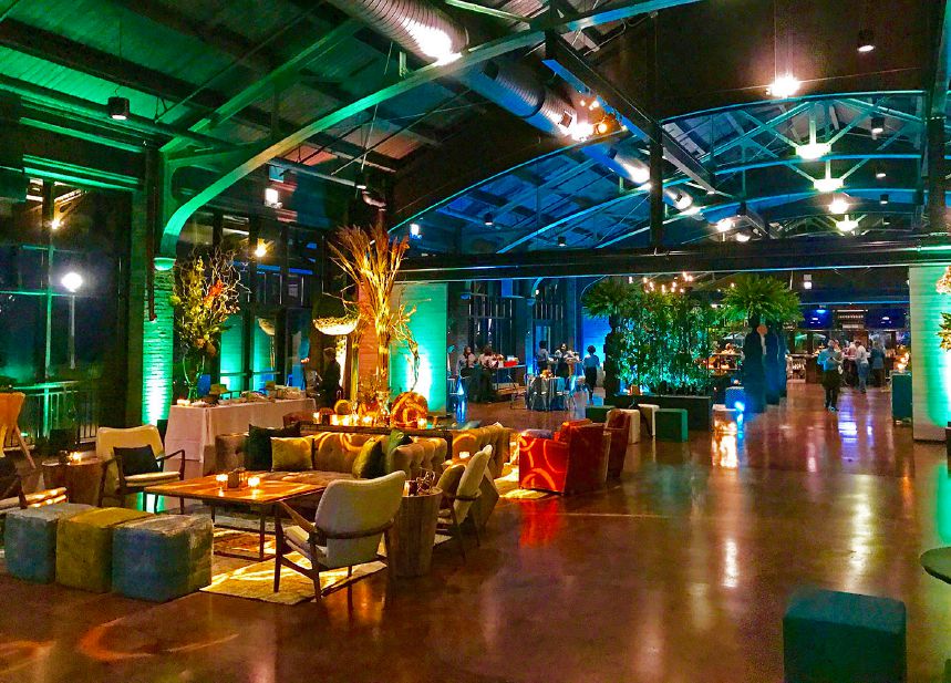
Much of the “new” event space was actually formed by enclosing the existing open-air pavilion (once used for barn dances and as a USO center for soldiers and sailors) and making it available for year-round use. In addition, flexibility was provided by installing moveable partitions so the building could function as one open space or two spaces or three spaces, depending on need. Structurally supporting these new partitions efficiently, in a historically respectful and aesthetically pleasing way, posed several challenges.

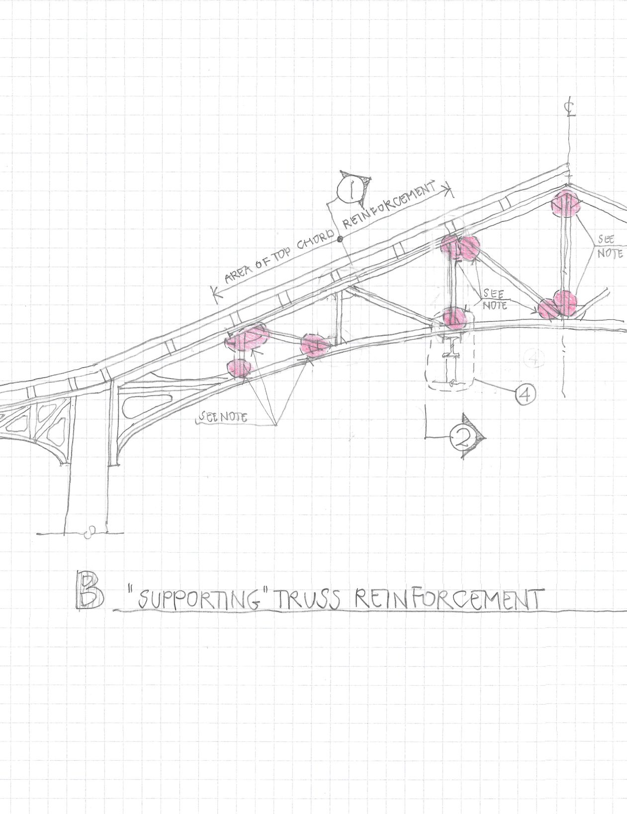
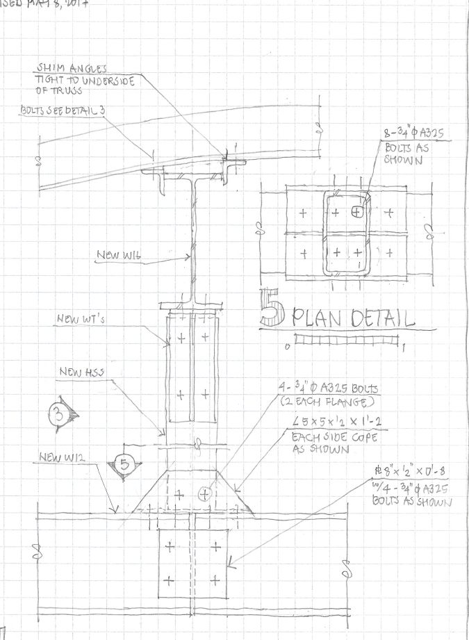
A closer look at the structural members added to the trusses at Theater on the Lake. These support the moveable partitions. The cross beam just under the trusses spans between two trusses, passing beneath the middle truss and not engaging, thus not overstressing, that truss. Shim angles brace the compression flange of the cross beam at the middle truss, allowing a lighter section with a flange width that equals the bottom flange width of the truss.
One of my first steps was to sketch the building’s existing support systems and graceful details, working out the stresses and forces in play, and how the original designers and builders dealt with them. Points that occurred to me as I sketched included the following:
• Existing structural systems included wood planking spanning to heavy-timber purlins bearing upon riveted, double-angle steel trusses spanning column to column; columns comprised of reinforced concrete encased in brick masonry; and piers bearing on pile caps atop timber piles.
• Enclosing the building would substantially increase wind sail—how would this affect existing structure?
• The existing lateral system partly depended on cantilevered, battered piers.
• It was difficult to tell exactly how the existing piers worked, as available drawings didn’t describe their reinforcing system, nor were there any extant as-built documents.
• The new moveable partitions would increase and redistribute the loads on the existing trusses and foundations.
• The exact size and condition of the existing foundations couldn’t be known without prohibitively expensive exploration.
Of course, these points would naturally occur to any structural engineer considering this renovation—I’m not suggesting that sketching is necessary for good design. I will note, however, that asking myself these questions while working methodically by hand greatly increased my confidence that I had, in fact, identified the critical factors affecting this particular engineering project. This example also shows that sometimes initial sketching reveals not answers, but questions, and knowing the right questions from the beginning is useful.
Not having original drawings pertaining to the pier-reinforcing system was a little troubling, but not a particularly novel problem. As the Concrete Reinforcing Steel Institute’s “Evaluation of Reinforcing Bars in Old Reinforced Concrete Structures (Engineering Data Report No. 48)” says in its opening paragraph: “Most practicing structural engineers sooner or later face the task of evaluating old structures. This task is always an interesting challenge, because it is never a routine application of the current practice in design. Owners commonly require re-evaluation when planning a change in building usage, restoration, additional stories or lateral additions in any combination. Frequently, the original contract documents, the ‘as-built’ revisions, and so on, cannot be found.”
In this case, “investigation” of the piers was needed—we ripped off some of the brick facade on the piers and saw for ourselves their condition and just how they were made. Other less-destructive examinations also were done. Working with this new knowledge, we assessed the battered piers and found sufficient capacity to support the additional wind loading caused by enclosing the building.
To make the space work as a multi-use venue, moveable partitions were introduced with glass and steel partitions heavy enough to provide acoustical separation between events. The weight and mobility of the partitions imposed substantial additional loads on the trusses and foundations that needed to be addressed structurally, and permitting impacts also had to be considered.
We found that the moveable partitions increased the loading on the foundations by just less than 10 percent. It was cost prohibitive to actually verify the capacity of the foundations, but the city of Chicago allows a 5 percent increase of foundation loading. Knowing that a number less than 10 percent, if divided by 2, yields a number less than 5 percent, the idea of sharing the partition loads between two trusses was born. A substructure system was developed to divide the load evenly between two trusses.
Returning to the truss design, we analyzed the new loading, determined allowable stresses and found that certain truss elements were overstressed. To compensate, I added additional angles to the top chord. I also stipulated replacement of original rivets with A325 bolts where required.
In the actual investigation and reinforcement of the trusses, I certainly used computer analysis. But the truss system, which was vitally important in the structural support and aesthetic appeal of this 100-year-old building now making a bid for iconic Chicago shoreline status, was mostly designed and constructed from hand-drawn plans. It has been very well received, but I recommend you go to a play at the theater or enjoy the year-round restaurant sometime and see for yourself.
West Town Residence
The subject of this project was a two-and-a-half-story, 4,300-square-foot single-family home built in 2007 in the West Town neighborhood of Chicago. The homeowners wanted to expand their living space with a third-story addition, but also needed to address certain lateral stability issues in the building that had not been properly addressed in the original design and construction.
Both goals had to be accomplished with attention to achieving a seamless integration with the contemporary aesthetic of the interior and exterior of their home. Indeed, despite the structural issues, this was a beautiful modernist urban residence, and I felt some personal responsibility to accomplish the work in a way that would respect the original architect’s intentions, meet the family’s needs and keep the building standing strong indefinitely.
Initial work sketching the various interacting structural systems—and trying to reconcile them with the proposed third-story addition—uncovered what became a major constraint on the project: although the new living space was the main focus of the project for the homeowners and my clients (contractors Integro Rehab), it quickly became apparent that the exterior work, including the structural reinforcement, was going to be the most critical and demanding element of scope.
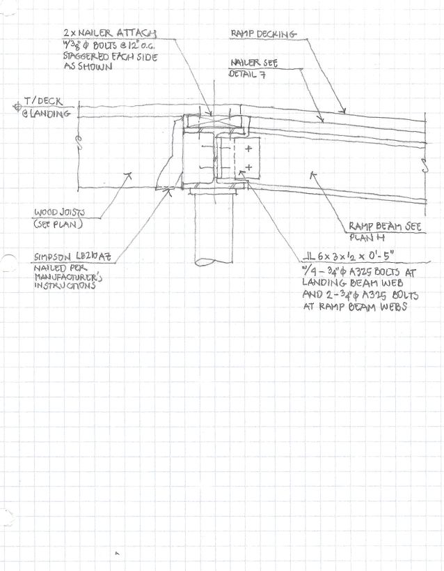
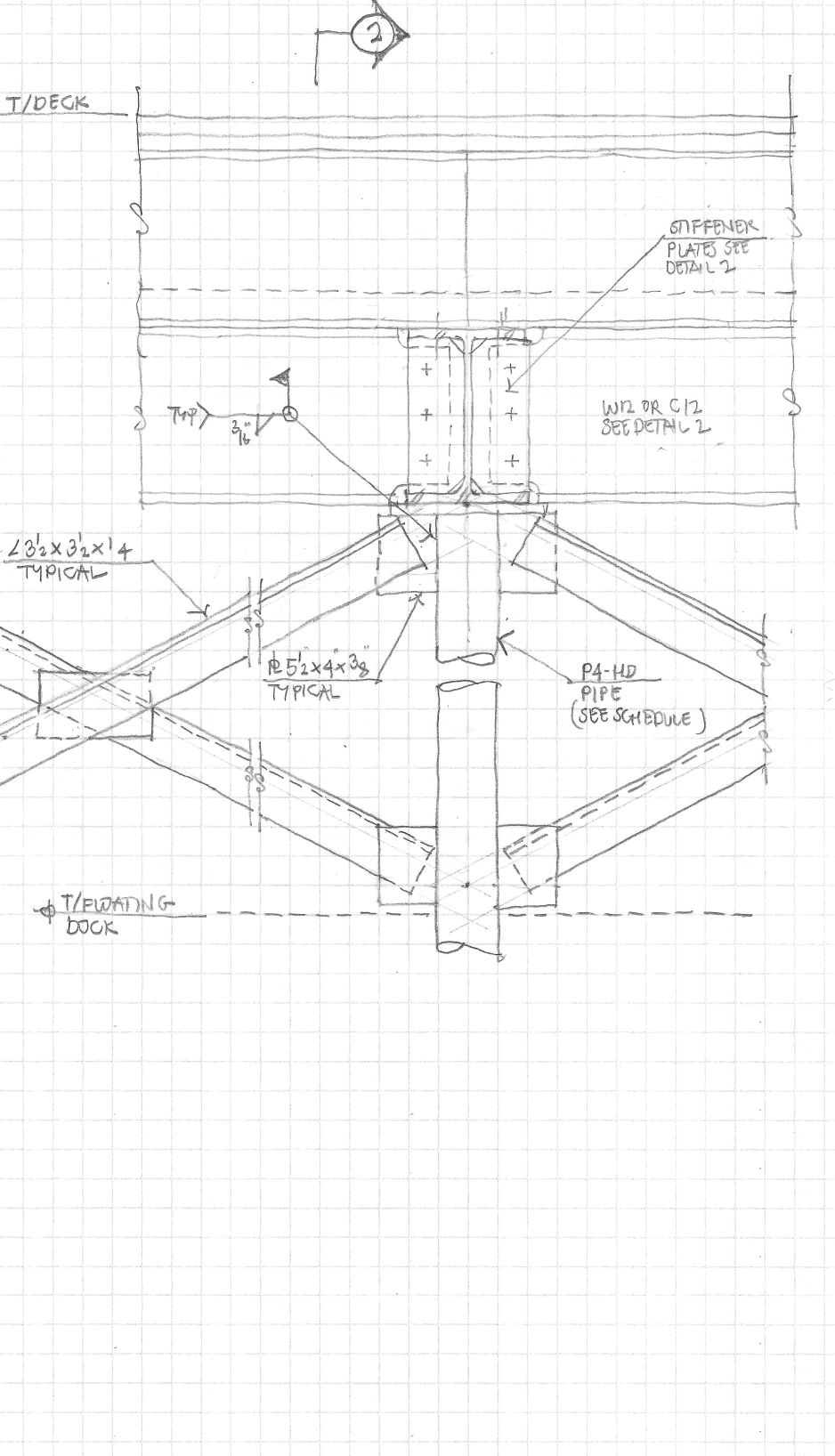
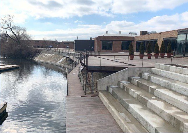
On the north branch of the Chicago River, this new deck structure includes seating areas as well as ramps that provide barrier-free access to the docks below. Serving a multi-use facility, boats can dock, allowing passengers to disembark and dine at the brewery or join the festivities at one of the many event spaces. As shown in the detail above and on the cover of the article, ramps and deck all are supported on a system of helical piles, with cross bracing providing lateral stability.
The addition was to be a living and study area for the client’s children, consisting of a living area, two bedrooms and one bathroom. The exterior roof spaces flanking both ends of the addition also were converted into functional patio and balcony spaces. The addition was accomplished (very) satisfactorily, and was a National Association of the Remodeling Industry (NARI) Contractor of the Year 2020 regional award winner. But actually constructing and supporting the addition required some deft and responsive structural work.
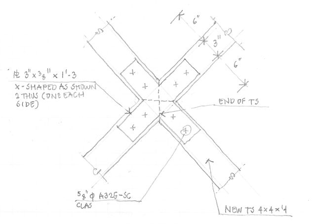
The major structural aspects of the renovation (actually more of a rehabilitation) were described by the contractor in its NARI award application: “The largest challenge by far on this project was to resolve the structural instability of the building while respecting the aesthetic integrity of the client’s home. The entire house was racking and needed to be stabilized through the addition of significant structural reinforcement at both the front (south) and back (north) of the house. A custom-fabricated x-brace system of steel beams on the south side was able to be installed on the interior of the facade and hidden by drywall, but on the north side, an even more-expansive reinforcement system needed to be installed in plain sight, on the exterior of the building.
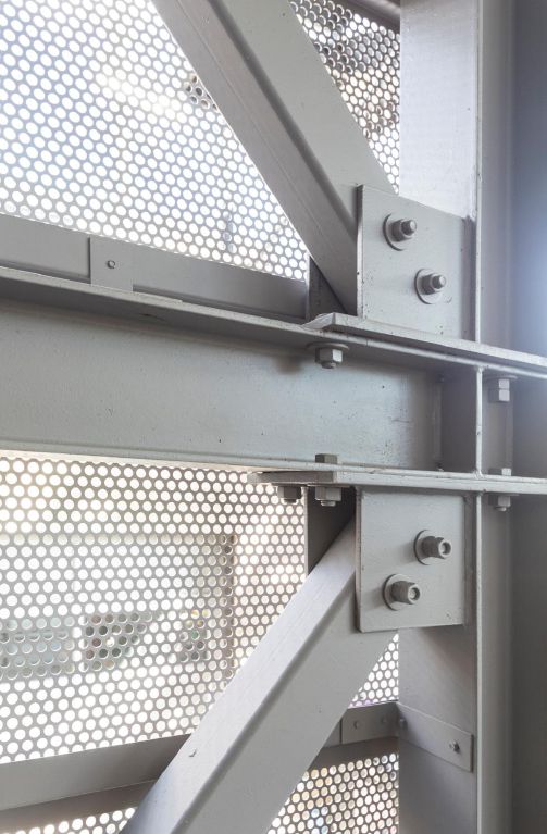
“Our solution was to mask this industrial-looking, steel x-brace system spanning the entire vertical elevation of the building with custom fabricated decorative panels. These screen-like panels not only convert a potential eyesore into an aesthetic accent, but they also serve a practical role by allowing light into the home and residents to see out of their home. The creation of this aesthetic and structural solution as well as its installation was only achieved through close collaboration and coordination with the structural engineer and the steel fabricator.”
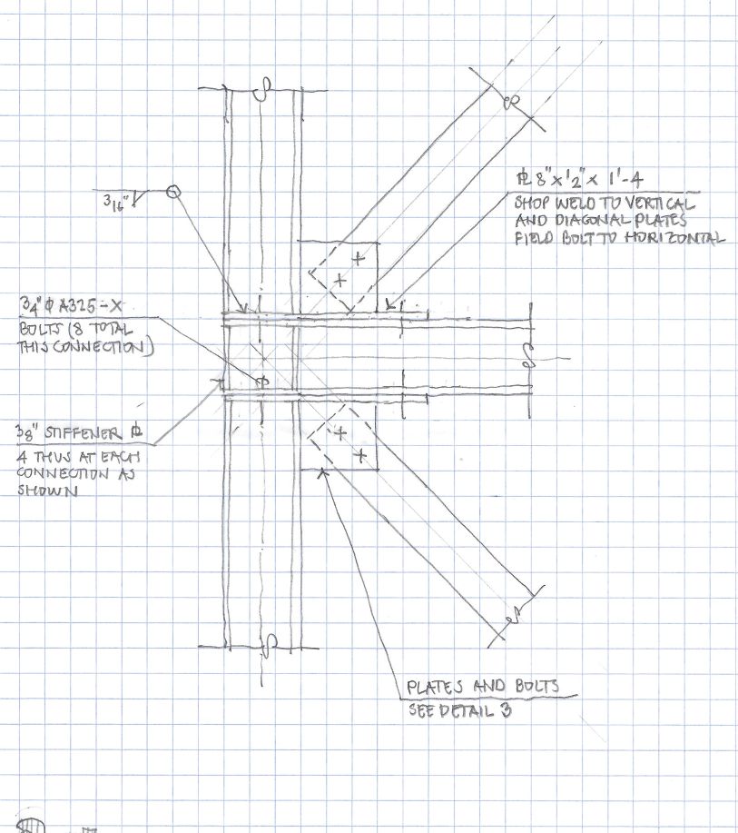
For the West Town Residence, lateral stability was provided by a system of x-braces. These were designed to be fabricated in the shop, such that all parts could be lifted by two workers and field bolted in place. Vertical and horizontal members with the required connecting plates were welded in the shop. These components were then lifted into place and bolted together with no requirements for field welding.
Working out the x-brace system in a way that satisfied structural requirements, aesthetic integrity, the homeowners and the contractor was a demanding task, and success was a direct result of careful, methodical work facilitated by much creation and analysis of hand-drawn sketches and plans, multiple site visits, and many meetings with the contractors. In the end, it became a professional accomplishment of which I am very proud.
The installation of this was a complex and severely constrained aspect of design and construction. Again, from the award application: “The installation of these (x-brace) reinforcement structures was complicated by the logistical limitations of the site. The ideal way to install the steel structural components would have been to fabricate the steel structure offsite as one piece and install it with the assistance of heavy machinery; however, both the interior installation in the south facade and the exterior installation on the north side had no room to accommodate the necessary heavy equipment. Only human power was available for both installations. As a result, we asked the structural engineer to redesign their original plans to break the structural system into small-enough components that they could be lifted by hand and assembled onsite. The lack of heavy lifting machinery also necessitated that the installation had to proceed from the bottom toward the top. The preferred sequence to avoid errors would have been to assemble it from the top down.”
All these complicating factors increased the need for precision in the design, fabrication and installation of the steel reinforcement structures. Any small discrepancies would have had major ramifications.
• Every detail was specified by the structural engineer.
• Each piece had to be precisely fabricated to fit perfectly.
• Every step of the installation was a collaborative effort between the contractor, fabricator and engineer.
This laborious redesign of the x-bracing system from a few large, welded elements into many small parts suitable for offsite fabrication and onsite piecemeal assembly in difficult conditions is just the sort of work where “mistakes cascade,” as Stewart Brand puts it, potentially resulting in catastrophic delays where all involved lose their composure, not to mention money and a construction season. And design for fabrication and assembly is something of a specialty where computer-aided drafting and modeling is held to be especially useful, if only for precision and clash detection. My many and detailed hand drawings helped understand the conditions, find ways to address the issues structurally and visually explain how the steel reinforcement structure was to be fabricated, assembled and installed.
Enabling a Deeper Understanding
Hand drawing can seem to be a relic from the past: a slower, more craftlike means of communicating. But the process of drawing something by hand—picturing it in your mind to the extent necessary to commit it to paper—can offer a deep understanding of the issues and provide the means to solve things in a thoughtful and appropriate way.
Skill and interest in drawing certainly can make the experience rewarding, but they aren’t necessary to enjoy the benefits of hand drawing. Although I wholeheartedly embrace technology in most of my practice (finite-element analysis is not something that lends itself well to hand calculation), I also embrace, wholeheartedly, the lower-tech methods of hand drawing.

Visit bit.ly/2WEZlZV to watch a follow-up webcam video interview of Clark Baurer recorded by Todd Danielson, Informed Infrastructure editorial director.

Clark Baurer
Clark Baurer, S.E., has a wide variety of structural engineering experience, including five years as a project structural engineer for SOM; two years teaching structural courses at the University of Illinois School of Architecture in Versailles, France; more than 20 years directing the structural engineering divisions for two Chicago architecture firms; and six years as a sole practitioner with Clark T. Baurer Structural Engineering; email: [email protected].
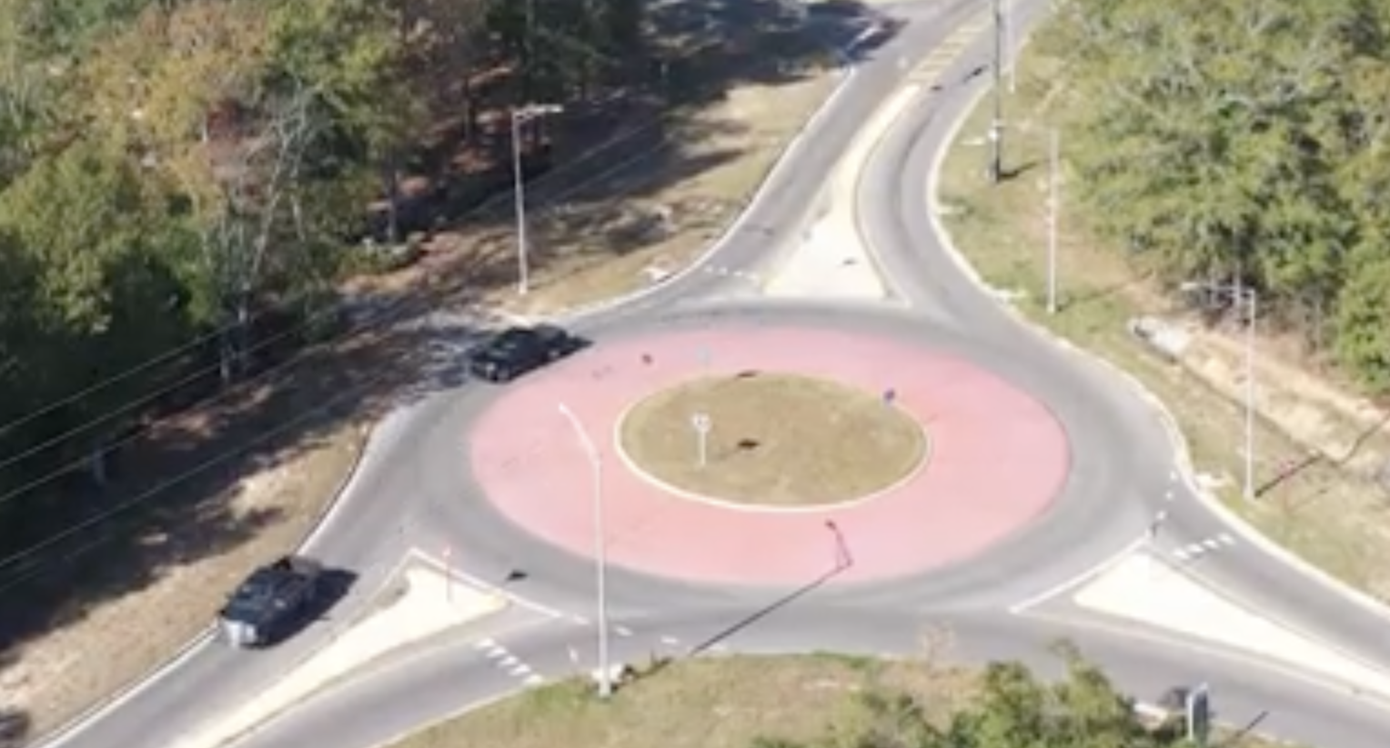
Video: New Roundabout Under Construction at McIver and Old Florence Roads in Darlington County
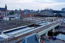
Bridge Replacement at Amsterdam Centraal Station
June Issue 2026
.jpg?width=225)