
All residential development projects encounter problems and complications. Some are expected, but most are not. The Summerlake subdivision in Wintergarden, Fla., required maintenance and mitigation due to unexpected construction delays that allowed cracks to form in the roadways. The following article looks at how these problems were identified, evaluated and mitigated using geotechnical engineering and drainage technologies.
In early 2008, the internal roadway within the Summerlake subdivision was constructed with a soil-cement base. However, development of the residential lots was delayed due to a housing recession—the residential structures within this portion of the subdivision were only built out in 2015. After the lengthy delay, the roadways were showing signs of block cracking with localities of significant seepage and pumping of fines through the base and at the curbs (see above photo).
Site Evaluation
An evaluation was performed to determine the root cause of groundwater-related pavement distress as well as recommendations for retrofitting. The evaluation revealed seven areas manifesting signs of groundwater-related pavement distress (see Figure 1).
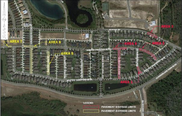
The seven pavement segments are as follows:
• Area 1: A portion of Red Crossbill Street (approximately 180 feet from the midpoint of the road and southward toward its intersection with Spotted Sandpiper Boulevard).
• Area 2: A portion of Bahama Swallow Boulevard (approximately 380 feet between the intersections of Red Crossbill Street and Spotted Sandpiper Boulevard).
• Area 3: A portion of Porter Road (approximately 220 feet between the intersection of Spotted Sandpiper Boulevard and Key West Dove Street).
• Area 4: White Pelican Drive (approximately 525 feet) and a portion of Bahama Swallow Boulevard (approximately 225 feet).
• Area 5: A portion of Pacific Loon Street between Bahama Swallow Boulevard and Spotted Sandpiper Boulevard (approximately 380 feet).
• Area 6: A portion of Atlantic Puffin Street (approximately 460 feet) between Bahama Swallow Boulevard and Spotted Sandpiper Boulevard, and a portion of Bahama Swallow Boulevard (approximately 225 feet).
• Area 7: A portion of Bahama Swallow Boulevard (approximately 65 feet) west of the intersection of Spotted Sandpiper Boulevard.
Three of the seven locations (1, 2 and 3) correspond to significant elevation changes in pre-development landscape, with transitions from moderately drained soils on the higher ground to poorly drained soils at the lower end.
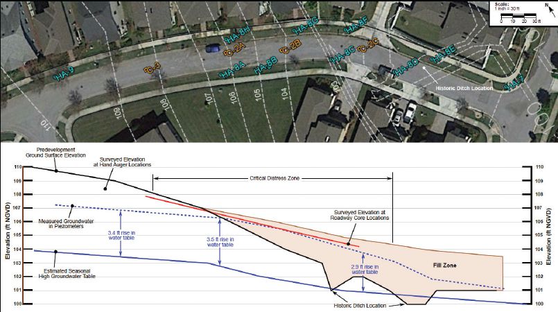
It was revealed that Area 2 was within a wetland bed. During development, a dewatering ditch system was constructed prior to backfilling the ditch area for roadway development and lot-terraced construction. Moreover, Area 2 showed a drastic rise in the water table at the location of the former ditch, and it experienced the most-severe groundwater pumping and seepage. The drastic rise in the water table elevation at Area 2 (see Figure 2) is caused by the following factors:
• Backfilling of pre-development ditches, which resulted in an approximately 3-foot rise in the water table at this location. The water table was measured at the very start of the 2017 wet season.
• Very permeable fine-sand layers on this slope that transmit groundwater at high flows, which may render conventional underdrains ineffective.
• Over-irrigation due to the heavy watering of lawns.
• The distressed zones are within a former wetland bed with remnant underground shapes, which encourages seepage toward this locality; boring in this area disclosed muck.
• Lot grading in the locality provides a recharge source, because these lots are terraced and channel subsurface water toward the roadway.
Solutions
Groundwater-related distress is much less severe at all other areas than Area 2. The recommended solution at all these other locations is to construct standard underdrains located in the landscape areas along each side of affected portions of the roadway for each area (see Figure 3).
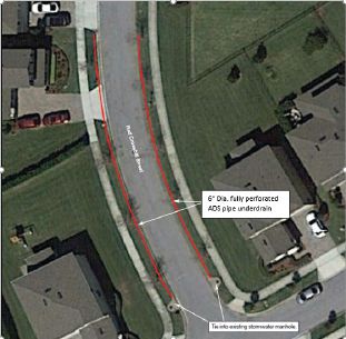
The standard underdrains would consist of 6-inch fully perforated ADS pipes with the center of the underdrain pipes located 2 feet behind the roadway curbs. The underdrain pipes would be wrapped with fabric sock and encased within 18-inch-wide by 30-inch-deep sand filler. The underdrain pipe invert will be 30 inches below the top of the pavement at the curb line and 6 inches above the bottom of the sand filler.
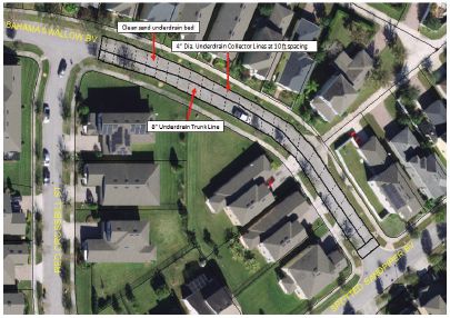
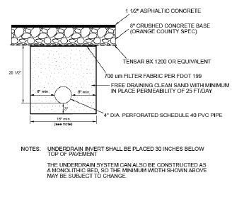
With respect to Area 2, more-extensive groundwater interceptions were necessary, including reconstructing the pavement with an underdrain bed below. The new pavement was constructed with a 1.5-inch asphaltic concrete surface layer underdrain by an 8-inch crushed concrete base. A layer of geogrid also was recommended below the base material. The underdrain bed consists of 23.5 inches of free-draining sand with minimum in-place permeability of 25 feet per day. The underdrain bed will be wrapped with filter fabric and overlain with 4-inch-diameter fully perforated ADS underdrain pipes perpendicular to the roadway at a spacing of 10 feet on center.
The underdrain pipes would be wrapped with fabric sock, and the underdrain pipe inverts will be 3 inches above the bottom of the underdrain bed. An 8-inch trunk line is required to connect the underdrain pipes and discharge the groundwater flow to the receiving system (see Figure 4).
Results
Currently, all the underdrains—including the driveway approaches in Areas 1, 3, 4, 5, 6 and 7—have been constructed at a total cost of $152,000. The intriguing reconstruction of Area 2, where the underdrain array would be placed within the roadway area, was also completed at a cost of $187,000. Various problems—including a utility-conflict high-water-table impact, which had to be mitigated by well point, as well as a few frustrated citizens upset about the project’s pace—were cordially resolved.
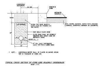
Figures show a typical cross section of curb line roadway underdrain for Areas 1 and 3 (top) and the underdrain detail for Area 2 (bottom).

Deodat Budhu
Deodat Budhu, P.E., is the manager of the Orange County Roads and Drainage Division; email: [email protected].
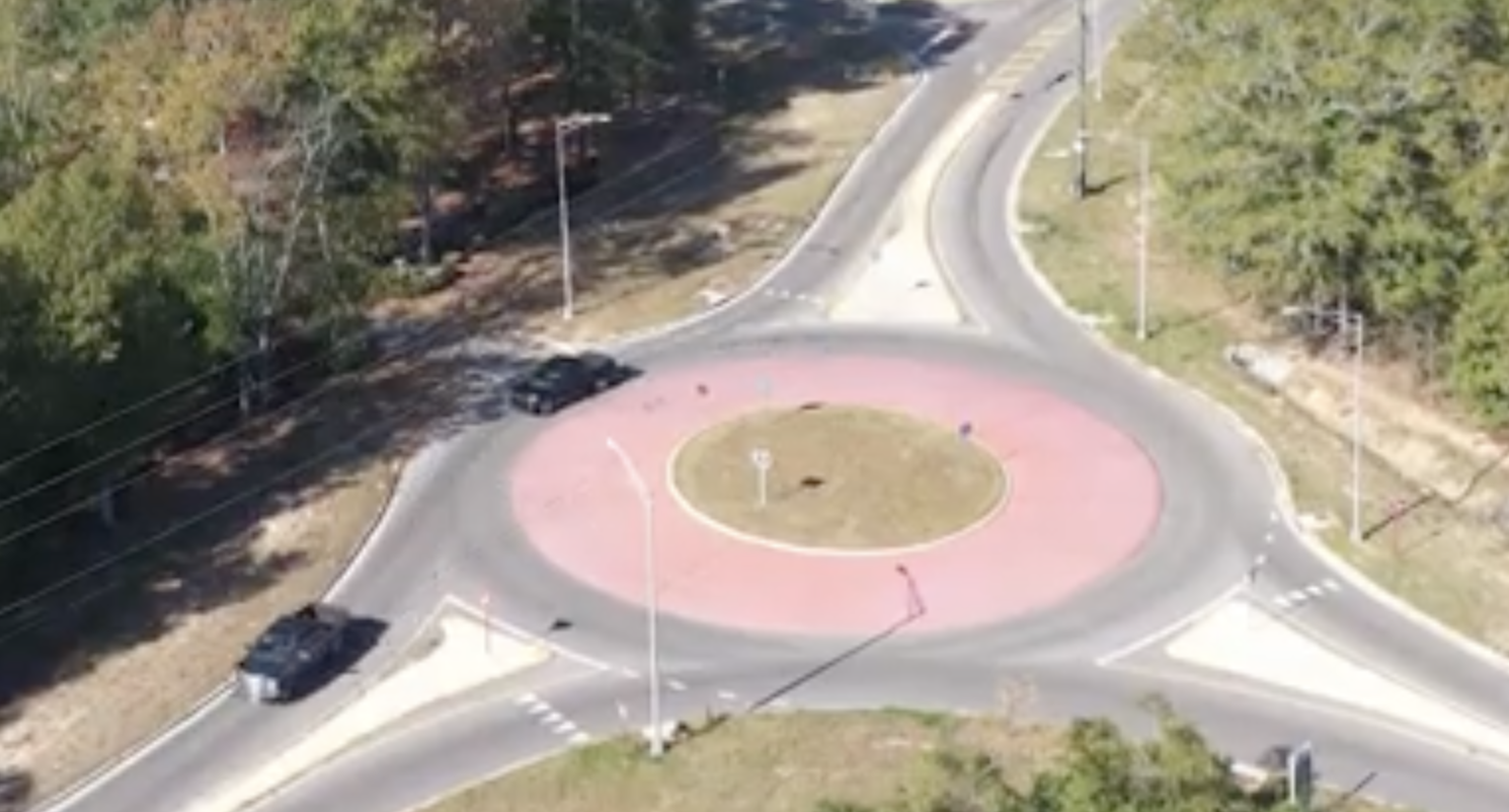
Video: New Roundabout Under Construction at McIver and Old Florence Roads in Darlington County
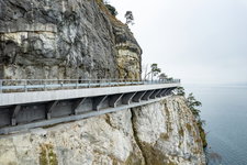
K2b Cantonal Highway
June Issue 2026
.jpg?width=225)