By Mark Scacco, P.E.
In 1852—the year women were being arrested for wearing pants (Emma Snodgrass in Boston) and the first edition of Peter Roget’s Thesaurus was published—the Erie Railroad Company built the first bridge to cross the Genesee River Gorge in what would eventually become Letchworth State Park in Western New York, about 60 miles east of Buffalo. Claimed to be the world’s largest timber bridge, it served the rail line until it burned to the ground in May 1875.
In June and July 1875—the same year Jesse James robbed a train in Missouri, the first Major League baseball shutout was recorded (Chicago 1, St. Louis 0), and Alexander Graham Bell made the first sound transmission—Erie Railroad built a new single-track iron railroad bridge to replace the original. For the next 140 years (with strength upgrades occurring in 1903), the Portageville Bridge would serve as a vital rail link for Erie and the surrounding region.
As the 20th century drew to a close, the current owner of the rail line and bridge, Norfolk Southern, determined the bridge was nearing the end of its useful service life and had become a weak link in the system: it was weight-restricted and couldn’t carry the 286,000-pound cars, which are common today, and train speeds crossing the bridge were limited to 10 mph. In 1998, Norfolk Southern hired bridge engineering firm Modjeski and Masters for preliminary studies on the bridge.
A Century of Design
Founded in 1893, Mechanicsburg, Pa.-based Modjeski and Masters has been designing bridges for 125 years. With 11 offices stretching from New Jersey to Louisiana to Colorado, Modjeski and Masters has built a reputation as one of the country’s premiere bridge engineering companies. This long heritage of design would prove useful as the New Portageville Bridge project moved forward.
As part of its preliminary investigation, Modjeski and Masters looked at the feasibility of repairing the bridge or replacing it. In 2006, after several years and additional inspections, it was determined that replacing the bridge was the only feasible option.

“During the preliminary phase, we considered three design options,” explains Daniel B. Irwin, P.E., senior engineer, Structures, Modjeski and Masters. “Our study included replacing the existing bridge with a similar trestle bridge, a two-span truss bridge or a spandrel-braced arch bridge.” The existing bridge and track would need to remain operational throughout construction, so the new bridge would be built on a parallel alignment.
Each alternative was analyzed and compared on several factors, including cost, constructability and visual impact. Although Norfolk Southern had the final decision in deciding what type of bridge would best meet its needs, they were required to submit to a rigorous environmental permitting process. Due to the viewshed’s high value and the impact any new bridge would have on the scenic area, the review required preparing alternatives for presentation to and gathering of feedback from the public to help decide what type of bridge would replace the existing iconic structure.
Permits and More Permits
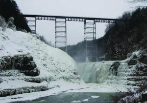
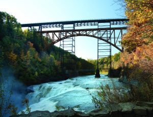
More than 1 million people visit Letchworth State Park each year, and many come to view the gorge and bridge. Located immediately upstream of three waterfalls, it’s one of the most popular and scenic areas in the park.
When the decision was made to remove and replace the existing bridge, Norfolk Southern knew it had significant permitting challenges ahead. Although the bridge was privately owned by the rail line, its location in the middle of a public state park would require environmental, historical and cultural-resource permits.
New York’s State Environmental Quality Review Act (SEQR) requires all state and local government agencies to assess the environmental significance of all actions they have discretion to approve. SEQR requires the agencies to balance environmental impacts with social and economic factors when deciding to approve a project.
“We were lucky to work with New York State DOT in a PPP [Public Private Partnership] to look at replacing the bridge,” says Howard Swanson, Norfolk Southern assistant chief engineer. “The existing bridge had substantial weight and speed limits, and the New York DOT had identified it as a major bottleneck.”
After six years of coordination among Norfolk Southern, the state permitting agencies, the consulting team and the public, the environmental impact statement was approved in late December 2015.
Rendering Public Participation
Because of its location and high visibility, the New Portageville Bridge project differed from a typical private bridge replacement. The SEQR permitting process required public participation and feedback regarding the type of bridge to be constructed.
Therefore, multiple photorealistic renderings of the various bridge configurations were prepared. Due to the historic nature of the existing bridge, consideration also was given to converting the tracks to a pedestrian trail, and renderings included this option.
“The renderings were developed using Rhino Renderer and were used to aid in visual displays for the client and public,” says James T. Nugent, Modjeski and Masters director of marketing and business development. “They were also used to aid in a Visual Impacts Analysis (VIA) to assess potential adverse impacts to the scenic vantage points around Letchworth State Park.”
As the saying goes, a picture is worth a thousand words; with the aid of the visual renderings, the public was “overwhelmingly in favor of the arch span design,” adds Irwin. Ultimately, the decision was also made to remove the existing bridge. Although Norfolk Southern had offered the bridge for sale for only $1, no one stepped forward to commit to converting it to and maintaining it as a pedestrian bridge. Nonetheless, to preserve its heritage, parts of the existing bridge were donated to the state park, where they’re now part of an interpretive display.
Lay of the Land
As with all civil projects, prior to the start of detailed final design, the survey team must do their work. In the case of the New Portageville Bridge, this work fell into two main categories: 1) geospatial/design surveying and mapping, and 2) boundary and right-of-way research.
To gather the survey data in this challenging location, Shumaker Consulting Engineering & Land Surveying used a combination of data collection techniques. First, it contracted with an aerial survey provider who used fixed-wing manned aircraft (this was pre-drone 1998) to collect data for the overall base map of the area. The stereoscopic photographs were combined and correlated to produce a digital terrain model (DTM) with 1-foot contour accuracy. The base model was delivered to Shumaker as a Bentley MicroStation CAD file.
To add detail and fill in areas missed by the aerial collection, Shumaker employed standard data collection and modeling tools, including Leica reflectorless total stations and Bentley InRoads. “The gorge wall overhangs created special challenges in preparing the DTM,” explains Ammon Bush, L.S., vice president and senior manager, Shumaker Geomatics Division. “We used some fairly cutting-edge technology at the time, including GPS and reflectorless total stations. While commonplace today, 20 years ago, these tools were still very new and not in wide use. Some of the tools we used on this project were just hitting the market in the late 1990s.”
The base of each half of the arch bridge bear on the gorge wall rock. To accommodate the new structure, rock had to be blasted. To ensure the correct amount of material had been removed, Shumaker surveyed the gorge wall face and incorporated this into its base DTM model.
While the mapping team developed the surface models, the boundary and right-of-way group faced its own challenges as they researched the land ownership and property lines around the project area. Due to the age of the records involved—some dating back to the early 1800s—none of the records were digitized. This meant a lot of time was spent camped out at various locations to research and make sense of the records.
“We got help from Norfolk Southern, New York State Office of General Services and New York State Park records,” recalls Matthew Thompson, senior engineering technician and project manager at Shumaker. “The local county office was a key location for our research.”

Untangling property lines and ownership was a critical component to the project’s success. There are multiple stakeholders in the project area, including the state park, Norfolk Southern and private property owners, and Norfolk Southern was determined to identify all issues and come to fair and reasonable solutions to protect each party’s interests. This involved near-equal-area property swaps between the rail line and the park as well as a straightforward land acquisition from a private property owner. “Norfolk Southern stepped right up and was proactive in meeting with stakeholders and in laying out issues and coming to consensus on how to deal with them,” says Thompson.
The main challenge faced by the survey team was the project’s long duration. “We started preliminary work in 1998 and continued working on this project through construction in 2015,” adds Bush. “Norfolk Southern’s determination to get it done was a key success factor.”
The long duration presented a number of challenges related to technology. During the project’s 17-year span, Shumaker’s design software, hardware and field equipment were upgraded several times. Accessing and updating the digital models happened at least twice. “For the first major software upgrade, there was a lot of manual work required to move the data forward,” notes Bush. Further, midway through the project, as 3D models became more widely used, the surveyors had to invest in more-powerful workstations.
Civil and Bridge Engineering
With the site surveyed, property boundaries established, and the public and owner in agreement with the type of bridge to build, engineers at Modjeski and Masters moved into final design and tackled a number of challenges: some typical, some rare and others altogether unique.
When laying out the new bridge and approaches, it became clear they would have to relocate a road that ran beneath the existing bridge and through the location where the new bridge would bear on the west side of the gorge. The area also had pedestrian trails and viewing areas. The team was able to turn this challenge into a positive park improvement; the existing road had a dangerous blind curve that was eliminated in the new layout.
Site engineers also relocated a parking lot so it would be between the road and the viewing area, eliminating the need for pedestrians to cross the road after parking. In the process, they also were able to preserve some stone wall features and incorporate them into the new parking area. Bentley InRoads 3D models and visualization helped the team conceptualize and execute the design.
Throughout the project, tight collaboration among design team members, owners and public was a necessity. The new bridge and approaches were designed for a train speed of 35 mph, 3.5 times the speed of the existing bridge. The alignment on the gorge’s west side includes a spiral-curve configuration that requires superelevation. The civil design team worked through multiple iterations to arrive at a final alignment location, which directly impacted the bridge and bridge anchorage.
The scale of the bridge is difficult to visualize. It consists of 7.3 million pounds of Grade 50 steel, and the four arch bearings each measure 9 feet by 10 feet by 5.5 feet and include a 24-inch-diameter forged steel pin. The skewbacks for the arch are buried in gorge walls, which required significant blasting. The Modjeski and Masters civil team worked closely with the project geotechnical team, Golder Associates, to provide constraints for vertical slopes and treatment around the tops of the excavations. To do this, Modjeski and Masters shared InRoads DTMs as well as simple PDFs showing the alignment profiles.

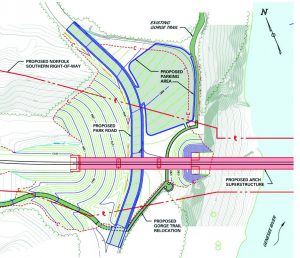
A 2D design document details the original bridge’s western approach (top) and the new bridge’s western approach with improved parking lot access (bottom).
While the civil team worked through the site design, bridge engineers were busy developing a design that was economical and buildable. It was in the design of the bridge itself where the rare and unique challenges arose.
Two-hinged arch structures are statically indeterminate (i.e., there are more internal and reaction forces than equilibrium equations). Because of this indeterminacy, the bridge would be subject to thermal stresses. The American Railway Engineering and Maintenance-of-Way Association (AREMA) is the industry body responsible for publishing guidelines for design, construction and maintenance of railroad infrastructure in the United States and Canada; due to their rarity, Chapter 15 (Steel Structures) in the AREMA design manual doesn’t provide much guidance in regards to indeterminate structures.

“This type of bridge is exceedingly rare for railroad use,” says Modjeski and Masters’ Nugent. “The last railroad bridge of this type in North America was the Michigan Central Bridge in Niagara Falls, completed in 1925.”
Fortunately, with its 125 years of experience, Modjeski and Masters had to look no further than its own design archives to find two examples of a similar structure: Crooked River in Oregon and Hurricane Gulch in Alaska. “Hurricane Gulch, the last bridge of this type with which Modjeski and Masters was involved, was built in 1921,” adds Nugent.

Based on its experience and in coordination with Norfolk Southern, Modjeski and Masters determined the bridge should be designed for the temperature range -30 degrees Fahrenheit to +120 degrees Fahrenheit, as defined by AASHTO for the region. It was further decided that because arch members would be under thermal stresses at all temperatures (except for the exact temperature when the halves were joined), thermal stresses would be considered under all stress conditions.
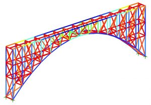

Being indeterminate, the bridge also would be subjected to stresses resulting from the settlement of its supports, so the geotechnical engineer performed a finite-element analysis of the bearing rock. These results, along with the thermal stresses and typical Cooper E80 train live loading, were incorporated into Modjeski and Masters’ 3D finite analysis of the arch span using LUSAS Bridge software.
A unique challenge faced by designers was wind loading. Norfolk Southern runs double-stack trains on the line that would use the new bridge. Although AREMA provides some guidance for wind loading, its current design doesn’t necessarily reflect the wind loading that a double-stack train would impart on a bridge. Therefore, the Modjeski and Masters team had to research double-stack equipment currently in use on railroads and develop the conservative loading of 600 pounds per linear foot acting 10 feet above the tracks. Discussion within AREMA Committee 15 of the work done by Modjeski and Masters on this project has been part of what prompted studies on how to incorporate double-stacked wind loading into Chapter 15.
Fabricate
After the bridge design was complete, the task of fabricating the members was taken up by Canam Bridges US. Using geometric models and plans from Modjeski and Masters, Canam used Trimble Tekla modeling software to create 3D models of the steel members, which then were exported to DXF files and imported into the fabrication equipment.
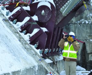
Due to the small project footprint, there was very little staging area to receive and store members shipped to the site. “The biggest challenge was getting the parts to the site,” says Tony Matutis, national sales manager with Canam. “Most of the parts were fabricated and shipped just-in-time.” Of particular interest was the massive, 30-ton bearing assemblies. The hinge and pin had to adhere to strict tolerances and were fabricated by JC Machine to within 30/1,000th of an inch.
Tight coordination among the fabrication team, Modjeski and Masters and the steel erector was key to success. “We work well together with [bridge erector] American Bridge and Modjeski and Masters,” says Matutis. “We had to coordinate the fabrication of the parts with the temporary tie-back system used during construction.” He also offered kudos to Modjeski and Masters: “They did a great job in the design and a tremendous job in laying it out. There were less than 30 RFIs [requests for information].”


Build
Construction of the new bridge broke ground in October 2015, and most of the team still was actively engaged. Surveyors from Shumaker staked property boundaries as well as proposed approach alignments. The alignment staking was used as a visual guide for a site tour for regulators and the public to show where the new railroad would go; the geotechnical engineer was on hand to assist with the tie-back anchorage system; and Canam Bridges US continued to coordinate just-in-time delivery of the members.
The as-submitted planset from Modjeski and Masters included a suggested construction sequence that the erector was free to utilize. Regardless of method, the erector was required to submit calculations for each stage to Modjeski and Masters to review. The eventual sequence selected by the erector was largely unchanged from the suggested construction sequence.
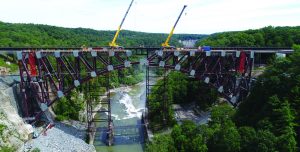
The plan called for erection of the arch as two separate cantilevers, with temporary tie-backs. The tie-backs themselves consisted of six large-diameter steel wire ropes anchored to the top of each side of the gorge. The tie-back, cantilevered approach eliminated the need for nearly all falsework.
Modjeski and Masters evaluated the structure using a non-linear, finite-element model for a variety of loading combinations and construction phases, including self-weight, wind loading and contractor loading. Non-linearity was required, because the stresses would redistribute as the structure transitioned from cantilevers during construction to an arch when the halves were joined and the tie-backs removed.
Working simultaneously from each side of the gorge, construction proceeded toward the middle where the two halves met. Riggers located on each side of the gorge were used to place the arch members until it could no longer reach the end of the ever-lengthening cantilever. At this point, rubber-tire cranes were located at the ends of the cantilevers to continue placing members. The contractor worked closely with Modjeski and Masters to verify the steel design could handle the construction loads and wind loading.
Strength and Beauty

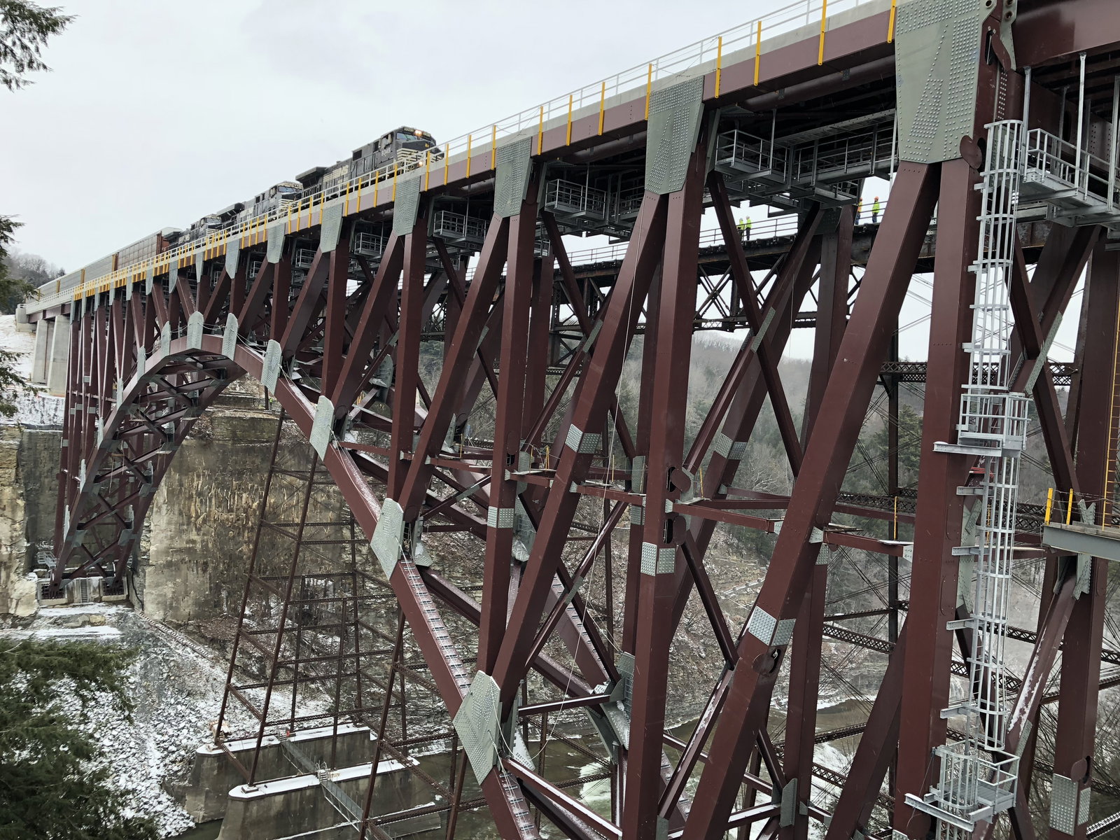
The $75 million bridge is an example of strength and beauty. Sitting 250 feet above the river bed below, the arch is 483 feet long with three, 80-footlong girder spans on each side, creating a total bridge length of 963 feet. All main arch members are Grade 50 welded steel boxes, and the main connections use 1-¼” A325 bolts. The arch bridge is constructed from 7.3Million pounds of Grade 50 steel. More Than 1,000 cubic yards of reinforced concrete were used for the arch skewbacks.
“Historic” and “Once in a Lifetime”
At 2:20 p.m. on Dec. 11, 2017, after nearly 20 years of investigation, permitting, design and construction, the first train rolled across the new bridge. In a statement, Norfolk Southern CEO James A. Squires said, “This is a very exciting day for Norfolk Southern and the future of freight rail service in New York’s Southern Tier region.”
Others on the team also expressed enthusiasm and gratitude for their involvement with the new bridge. “This is one of the most historic sites we’ve worked on,” says Shumaker’s Bush.
“I’m very fortunate to have worked on this project, because it greatly increased my understanding of environmental processes, and it was a great project team to work with,” notes Swanson with Norfolk Southern.
“It was exciting to work on a similar bridge [to the one Modjeski and Masters did in the 1920s],” adds Modjeski and Masters’ Irwin. “It was a ‘once in a lifetime’ opportunity, because this type of bridge and location are not common.”
Each day, approximately 12 trains cross the bridge, providing business opportunities to shippers from New England to the Midwest and beyond. And every year, thousands of park visitors admire the bridge set in the beautiful natural surroundings of Letchworth State Park.

Mark Scacco
Mark Scacco, P.E., is a 25-year veteran of AEC technology and design consulting. He is an AEC Industry Consultant with Scacco LLC and can be reached via email at [email protected].
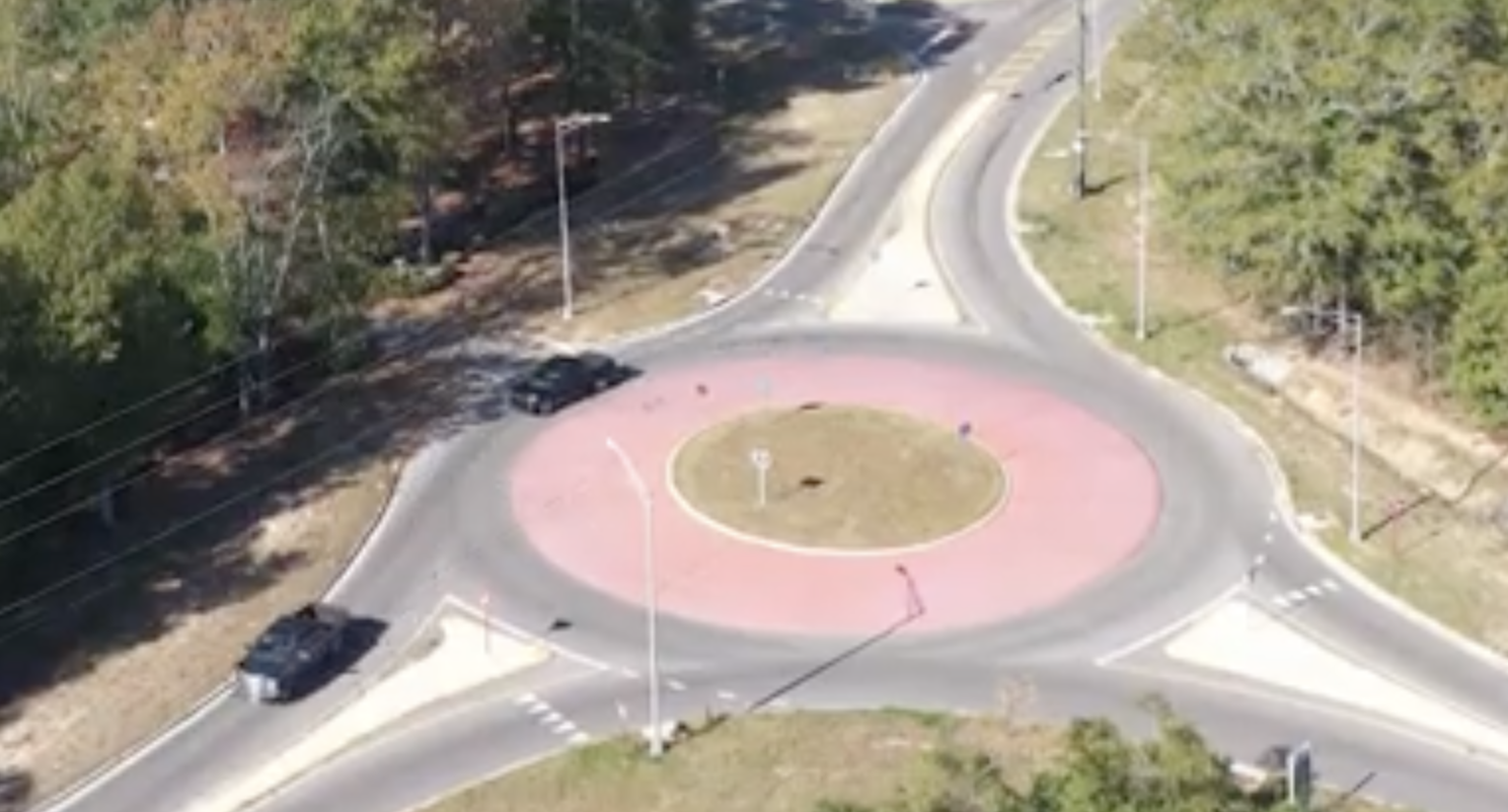
Video: New Roundabout Under Construction at McIver and Old Florence Roads in Darlington County
Froedtert Hospital Expansion

June Issue 2026
.jpg?width=225)