Since its initial release a few years ago, Autodesk InfraWorks 360 (IW360) has been received as an interesting software-development exercise in what a BIM application for infrastructure could look like, with some promising but limited functionality. Some robust features such as Model Builder, which enables users to quickly and easily compile data on existing site conditions, are powerful and were ready for “prime time” right from the start.
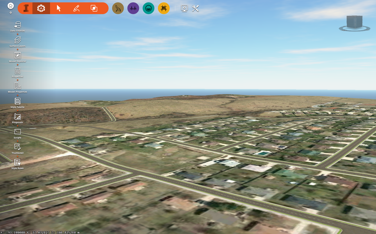
A project surface (top) was obtained from the Internet using Model Builder. The same project used a DTM created in Civil 3D (bottom) with a higher level of detail.
However, many of the other tools seemed to languish in an extended state of “for conceptual design only.” Fortunately for those looking to perform detailed design with InfraWorks 360, the latest release, InfraWorks 360 v2 Enhancements, is starting to deliver.
Accurate Base Model
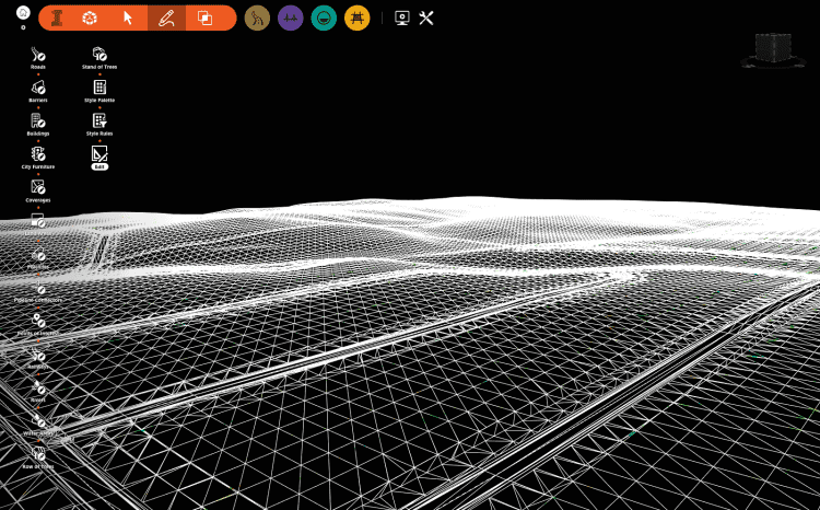
Nearly anyone interested in new technology for infrastructure design has probably seen a demonstration of InfraWorks 360 (if not, visit https://goo.gl/2nkLmk). These demonstrations typically include a segment showing off the ability of IW360 to fetch existing data from the internet and assemble them into a great-looking existing-conditions model. Although this is useful, the quality and accuracy of the data available on the Web, especially terrain model data, don’t provide an accurate base upon which detailed designs can be created.
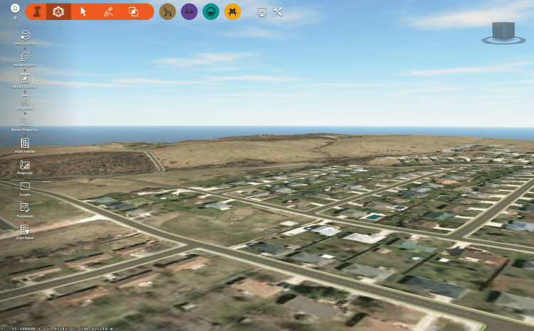
A Conceptual View (top) is compared with a Custom Design View (bottom).
Many of those new to IW360 may not realize that it can also import survey-grade terrain models for use as the existing-conditions base model. Highly accurate, detailed terrain models can come from a wide variety of sources, including DTMs created in Civil 3D and surfaces created from point clouds. Although not a new feature, this frequently overlooked capability is an essential first step in performing detailed design in IW360.
Units? Precisely!
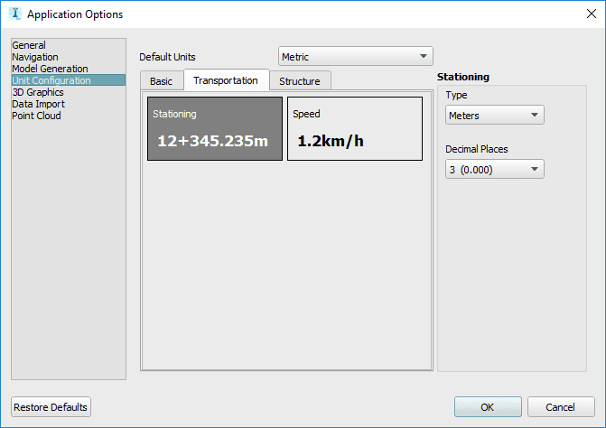
Digging into the new and extended features of v2, an important, yet easy-to-miss, enhancement is the update to model unit precision. In previous versions, the precision of units was set globally for the entire model. If you wanted lengths to four decimal precision, then everything else in the model would also be set to four decimals.
Users can independently set precision for various design elements.
With v2 Unit Configuration settings, the precision for 11 unit types can be set independently, including length, width, station, design speed, stress, moment and others. This is a major improvement for designing roadways. Users can now set the precision for PVI station and elevation to three-decimal precision, for example, and simultaneously set the roadway design speed to a more-practical precision of one decimal.
Design Like an Engineer
Another often-demonstrated feature of IW360 is the ease with which one can create compelling visualizations of existing and proposed conditions. With the ability to apply a wide variety of surface coverages, add city furniture such as hydrants and lamps, easily change building facades, etc., it’s easy to create stunning representations for communication with others. However, as a design engineer, this feature can be as much of a distraction as a benefit.
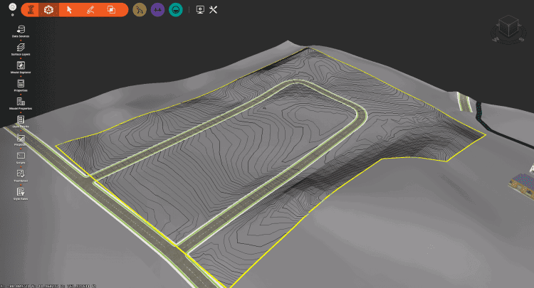
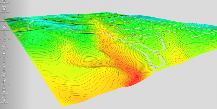
Terrain surfaces can be displayed with contours and elevation themes.
IW360 v2 Enhancements includes the ability to create and save different Visual Views. It ships with two predefined views: Conceptual View and Engineering View. The latter view turns off animation, realistic sky visualization and includes other setting adjustments, making it easier to focus on the design elements in the model. New Views can also be added with adjusted settings to meet specific user needs.
Furthermore, using improvements to Coverages, terrain contours can now be displayed and will update dynamically as the model changes. Although there are no contour labels, Terrain Themes can provide visual feedback on the varying surface elevations.
Detailed Roadway Design
No other area of IW360 v2 Enhancements received as many capability improvements as road design. With this release, civil and transportation engineers have a more-complete set of tools at their disposal; the most robust being Component Roads.
In previous releases of IW360, engineers had a limited ability to configure various design elements of a proposed road. Horizontal and vertical alignment geometry was manually drafted and, depending on the design speed associated with the road tool used (e.g., Local, Collector, Arterial or Highway), various other parameters such as minimum and maximum radius, spiral length, and tangent length were set based on predefined criteria. Component Roads extends these design capabilities, allowing users to add, delete and edit every component and assembly that makes up a road design.
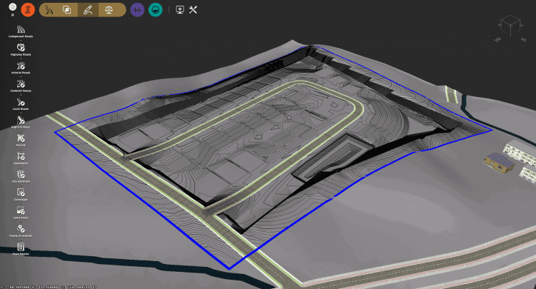
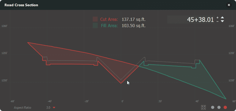
A road cross-section view shows cut and fill areas.
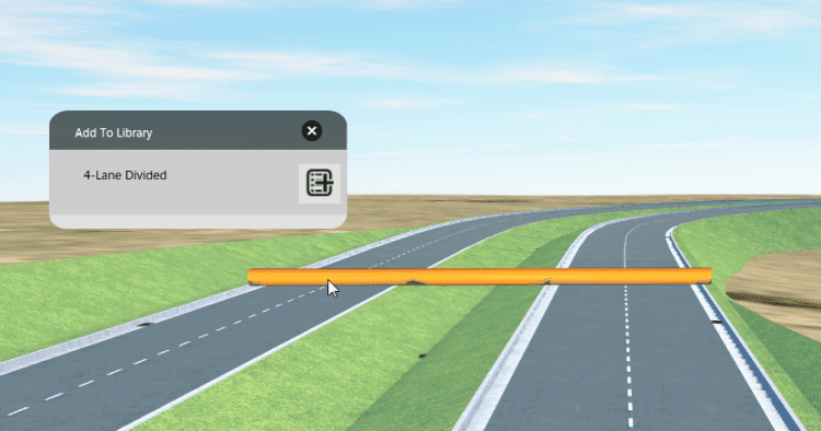
Rather than applying styles (a cross-sectional geometric template) to an entire road, users can now design roads in the context of the surrounding scene. Roadway-component variables such as material, width and cross-slope can vary by lane, and a different grading configuration can now be independently applied to each side of the road. For example, the right side of the road can be configured to tie into the existing terrain at a 3:1 slope, while the left side uses 5:1. After a roadway has been configured with various components, the user can add the customized road section to their library. The custom component roadway configurations are then available from the component assembly stack.
After a component road has been defined, it can be added to the component road library.
Another powerful addition to IW360 v2 Enhancements is cross-sections. Joining the profile viewing and editing features, engineers can now view cross-sections of roadway designs. Cross-section views display three types of information: 1) road assembly, 2) super-elevation, and 3) cut and fill areas.
Drainage and Pipe Sizing
The introduction of road components and super-elevation improves the automated creation and placement of inlet structures. When determining locations for inlets, InfraWorks 360 now takes into account the varying lane slopes as defined by the separate components and as required for super-elevations. This results in better placement of inlets along component roads based on cross-section locations of crown and sag, and super-elevation.
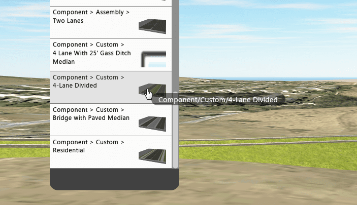
Custom component roadway configurations are available from the component assembly stack.
Under the hood, the Autodesk development team shared the drainage-calculation engine created for InfraWorks 360 with Civil 3D. This engine is based on the latest version of HEC-22 and calculates how much water each inlet captures, the required pipe sizes and energy profiles. With a shared engine, drainage results created in InfraWorks 360 and Civil 3D will be more tightly aligned.
Conclusion
The features added to the InfraWorks 360 v2 Enhancements continue its progression from a “conceptual design only” tool to one that’s looking more and more like a tool for detailed designs. Although there are still some notably missing features (annotation, sheet-set creation and detailed grading, to name a few), engineers and designers surely will welcome the advanced roadway design capabilities offered by component roads, flexible unit precision, engineering design views, enhanced automated drainage design, and the future features alluded to in the product roadmap and beta versions. Now seems like the perfect time to start learning the product before it gets too far out in front of you and your team.
Looking Ahead on the Roadmap
When shown new features, most users get excited and then immediately start asking for even more new features; I’m guilty of this as well. So I reached out to Sarah Cunningham, product manager with Autodesk, to learn what else is in the pipeline for designers and engineers. First, she pointed me to the InfraWorks 360 Roadmap at https://goo.gl/isoowQ.
“Moving forward, the development team will continue to focus on enhancing the product in four main groups: Design and Engineering Experience; Modeling and Analysis; Connected Workflows; and the Platform itself,” says Cunningham.
Specific capabilities InfraWorks 360 users can expect to see will enhance the ability to extract model quantities, review data and generate reports. This may include roadway quantities such as curb lengths/volumes; surface and subsurface material volumes; and bridge piers, girders, decks and drainage networks, including the quantity and type of junction, inlet structures and lengths, and diameters of pipes.
“When deciding what features to develop and release next, we make an effort to balance customer feedback with Autodesk’s long-term strategy,” explains Cunningham.
Users interested in learning more can request access to the InfraWorks 360 Rolling Sandbox beta by visiting https://goo.gl/kvrdWa.
Mark Scacco, P.E., is the editor in residence for Informed Infrastructure magazine, founder and president of Engineered Efficiency Inc., and since 2001 has been an AEC industry consultant working with firms to grow their business through efficient use of technology. Visit www.eng-eff.com to learn more, or reach him via email at [email protected].
Author
Mark Scacco
Mark Scacco, P.E., is a 25-year veteran of AEC technology and design consulting. He is an AEC Industry Consultant with Scacco LLC and can be reached via email at [email protected].


.jpg?width=225)