Tower of Power: Strong Steel Overcomes Constraints at a Tight Site
 In Chicago, one of the world’s architectural capitals, it’s not uncommon to see unusual buildings, innovative designs and creative construction techniques. The winds are strong, the soil is poor, and there are a lot of regulations and coordination required to build.
Overcoming the technical challenges associated with the unique design and construction of today’s highrises frequently is lauded by industry and the general public, as the buildings shed their boxy shapes and reach ever higher toward the sky. And a distinct appearance for these buildings has become somewhat expected. The undulating, sculptured quality of the Aqua building in Chicago; the twisted structure of the Evolution Tower in Moscow; the stratospheric heights of the Burj Khalifa in Dubai; and the wind-catching illusion of the Flame Towers in Baku, Azerbaijan, all look like they required special attention to achieve an intentionally unique design.
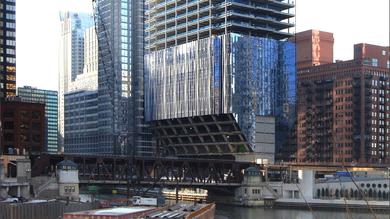
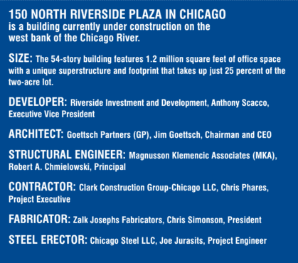
Such attention can similarly be seen in the new building at 150 N. Riverside in Chicago, which certainly has an unusual look, but it's an aesthetic driven almost solely by necessity. The challenges with raising this building on the edge of the Chicago River started long before the first design sketch was made or calculation performed: the plan called for a 54-story, 1.2-million-square-foot office highrise on a lot that hadn’t been developed since the early 1900s.
“This parcel was the last undeveloped lot on the river in downtown Chicago east of the railroad tracks,” says Tony Scacco, executive vice president for the developer, Riverside Investment & Development. “There are reasons the lot has remained more or less vacant for nearly 100 years.”
“This project had major challenges,” recalls Jim Goettsch, chairman and CEO of the project architect, Goettsch Partners Inc. (GPI). “First was assembling the site itself from three different parcels owned by the developer, the railroad and the city. Second was determining how to fit the building on the site and how to build it. And third was getting approval from the city. None of these was going to be easy.”

Challenge 1: Putting the Parcel Together
The project site consists of three distinct parcels owned by Amtrak on the west, the city of Chicago in the middle, and the parcel owned by the developer on the east, adjacent to the Chicago River. The plan called for building a publicly accessible open-space plaza above the tracks on the west, and placing the building as close to the river as possible on the east. This meant the developer would need to negotiate air rights with Amtrak and get approval from the city of Chicago.
Already a tight fit geometrically, regulations would make design and construction even tighter. By law, development must be a minimum of 16 feet from the tracks’ centerline and 30 feet from the river, leaving only a sliver-thin plot on which to construct the highrise. In addition, the closest existing building is a residential condominium tower only 120 feet away, and convincing these residents and their alderman to approve the project also would be required.
Challenge 2: Getting Everyone on Board and Obtaining Approval to Proceed
With the building footprint limited by the site geometry and setback requirements, the development team knew it would need a unique building. It had built similar buildings before, but never in the United States. In 2013, for example, GPI designed the Sowwah Square, a complex in Abu Dhabi that used a similar building concept. From the 54th floor down to the 8th, the building looks like a typical highrise. However, from the 8th floor down, the building tapers to a much smaller footprint. As one local resident described it, the building resembles a “tuning fork standing on end.”
Due to the unusual shape, the team needed to show the stakeholders and public what the project would look like when completed. This task would fall largely on the architect and its extended team. First, rough form and blocking models of the building concepts were prepared in 2D AutoCAD drawings, and 3D models were created in SketchUp and Rhino.
From here, three separate and equally convincing paths were taken to convey the design intent and demonstrate exactly what was proposed.
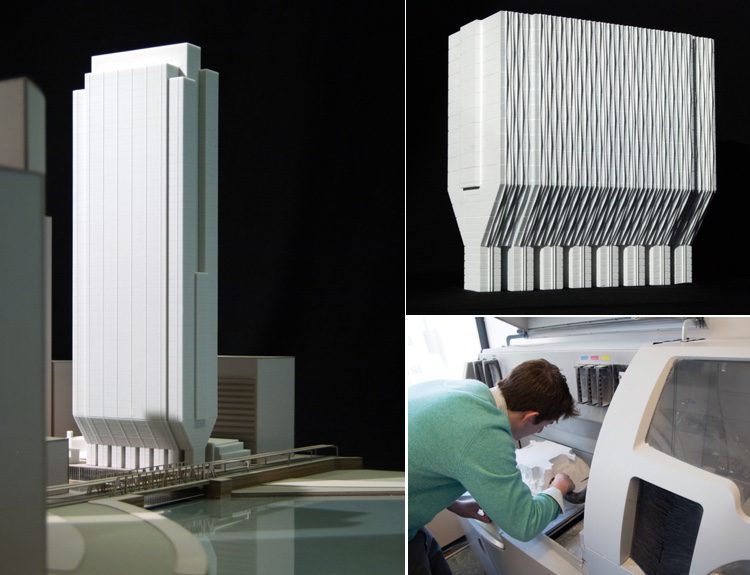
3D Printed Models
First, the architecture team at GPI downloaded the 3D digital models from Rhino to its inhouse ZPrinter 650 3D printer. Dozens of physical models were printed throughout the course of the project, aiding the design team’s experiments with a variety of options and helping them convey these ideas to the developer and general public.
According to Joachim Schuessler, principal with GPI, the printed models were used to “internally explore massing options for the tower and the podium spaces, and study and develop the facade system. We also used the study models to facilitate discussion with and communicate design ideas to the client.”
In addition, the models were an important tool for communicating with the public. “We printed models that were used to present the building to the client, to potential tenants and to certain city authorities, approval agencies and so on,” adds Schuessler.
Photorealistic Renderings
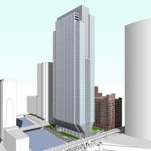
While the architect’s internal team worked on the printed models, the same SketchUp and Rhino base digital models were shared with the photo-rendering team. The renderings would be vital in explaining the project to the stakeholders and community, including residents in the adjacent condominium building.
Working with an offshore team of experts, GPI used Autodesk 3DS Studio Max to create realistic renderings showing the building itself as well as its location in relation to its surroundings, the plaza, the river and other highrises under construction in the area at the same time. Of particular importance was showing the residents and their alderman what the plaza above the railroad tracks would look like. This would prove critical in gaining their approval and allowing the project to move forward.
At a public hearing where residents had the opportunity to speak out about the project, many renderings from a variety of viewpoints were shared with the community. Expecting some pushback from the residents in response to constructing a 54-story office building 120 feet from their balconies, the team was surprised to not hear from a single resident who voiced an objection.
“They were enthusiastic about the project,” says Jim Goettsch. “By covering the tracks with a landscaped plaza, the project reduced the noise and diesel pollution. Many residents thanked us for improving their property values.”
Marketing Animation
Even with the residents, city and Amtrak all on board, the project was going nowhere without tenants. While the project team worked on gaining approval, the marketing team at Riverside Investment & Development was working to ensure the building would be occupied. To help with this, the team again turned to realistic visualizations, this time in the form of animated flythroughs of the building and surrounding metropolitan area. To make the site come to life before the first shovel turned, Scacco enlisted the expertise of Canada-based commercial real-estate marketing firm, ARCeSTRA.
“The client had to start marketing efforts for this project very early in the process,” says Spencer Rand, director of Professional Services at ARCeSTRA. “In developing our animations, we work through a five-phase process, the first of which is gathering whatever information we can. We initially started with PDFs of sketches and JPEGs, and as the design team progressed, we then worked with AutoCAD drawings and eventually the 3D SketchUp models.”
Using the design files as reference, Rand and his team created models in 3DS Studio Max with the VRay plugin. They added additional detail with Adobe After Effects. The result is a flythrough of the city, building plaza, parking garage, lobby and riverwalk.
“The animations were a valuable marketing tool which helped our potential tenants understand the look and feel of the completed project,” says Scacco.
Challenge 3: Design and Construction on a Small Parcel
From the start, everyone involved with the project knew the design and construction challenges of building an economically viable building on this tiny parcel were going to be significant. The parcel’s buildable portion is only 85 feet wide, there’s little room for construction staging, and the soils adjacent to the river channel are questionable at best. To complicate things further, Amtrak placed severe restrictions on when work could be done above the tracks.
“The logistics of the site were one of the biggest challenges we faced on this project,” says Chris Phares, PE, project executive with the general contractor, Clark Construction. “We were only allowed to work above the tracks overnight between 1:00 a.m. and 5:00 a.m.”
So Phares coordinated the construction logistics with Amtrak using various tools. “We used 2D CAD drawings and 3D Revit models to show them how construction would proceed as time passed.”
Another significant hurdle was figuring out how to design and build a 54-story building to fit on a postage-stamp-sized lot. According to Rob Chmielowski, PE, SE, principal with structural engineering firm Magnusson Klemencic Associates (MKA), “a typical building of this size requires a core roughly 45 feet wide. The design also had to meet the developer’s needs to maximize the rental square footage. We have a lot only 85 feet wide, so we needed a different structural system.”
Foundation and Core
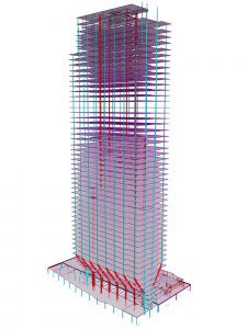
The core resisting the lateral loads and the foundation carrying the gravity loads would need to be concentrated into a smaller footprint than normal—both would have to be bulked up.
First, the core was elongated, and the walls were thickened to four feet. The walls themselves were to be constructed of 12 ksi reinforced concrete, with specifications defined not only for strength, but also for stiffness. This massive concentrated load would be carried on a reinforced concrete mat 150-feet long by 40-feet wide by 10-feet thick.
The mat itself caps 16 caissons, each a 10-foot-diameter steel tube filled with concrete extending 110-feet deep and socketed five feet into bedrock below. These are the largest caissons in Chicago, carrying gravity loads of 28 million pounds. The caissons also resist the lateral loads applied by the Windy City by vertically cantilevering above the Chicago River. When these overturning effects of wind are included, the caisson load jumps to 45 million pounds, pushing right up against the load capacity limits of the bedrock below.
[nggallery id=7]
The geotechnical engineers for the project, GEI Consultants, ran more than 860 different load cases when analyzing the tower’s foundation. High above ground level, at the top of the building, water-filler tuned-mass dampers work to reduce the natural sway of tall buildings, providing a strong yet pleasant work environment.
A smaller core presented challenges beyond structural considerations, even limiting the number of elevators the building could accommodate. However, the innovative design provided enough floor space for the typical population of a highrise of this size, moving the same number of people with a limited number of elevators. To accomplish this, the architect coordinated closely with elevator engineers and deployed a “destination dispatch” people-routing system, which reduces the number of stops and increases transport capacity by intelligently routing riders to elevators.

Steel Truss Design, Fabrication and Erection
Along with the typical design and construction challenges associated with erecting an office building, limitations on the building footprint meant the steel structural system supporting the upper floors would require special attention, from design to fabrication to erection. The tremendous gravity loads from the 54th through 8th floors would be transferred to the building’s core via a massive steel-truss system. The 16 wide-flange sections transferring this load each delivered 8 million pounds of force to the core. To meet the challenge, engineers would specify some of the largest steel sections in the world.
[nggallery id=8]
Adding to an already complex project, the developer’s move-in arrangement with the anchor tenants demanded an aggressive construction schedule. Tight and effective collaboration and coordination among the developer, structural engineer (MKA), general contractor (Clark Construction), steel fabricator (Zalk Josephs Fabricators) and steel erector (Chicago Steel LLC) would be critical.
“For budget and schedule reasons, the developer was buying steel before the design was done,” notes MKA’s Chmielowski. “There was no room for errors.”
Starting with design CAD files from the architect, MKA began modeling the building in Revit Structure. These models then were imported into RAM Steel to design and analyze the gravity system. Analysis of the lateral loads was done using eTabs and SAP from CSI. As the design came together, the size and complexity of the required truss gradually came into focus.
“It would be impossible to iterate through the design and analysis permutations without these software applications,” says Chmielowski. “However, it’s vital a qualified engineer is interpreting the results and guiding the process. Without that, you have garbage in and garbage out.”
Throughout the design process, MKA engineers worked closely with the fabrication team at Zalk Josephs. Information exchange was multichannel, using PDFs, hand sketches, conference calls, Web meetings and good ol’ fashioned face-to-face meetings. Special attention and collaboration occurred in relation to the connection details. By forgoing welded connections in favor of bolted ones, the team was able to reduce onsite construction time and costs.
As the design progressed, MKA shared its Revit models with Zalk Josephs. Using the models and 2D CAD drawings as a reference, Zalk President Chris Simonson and his team modeled the entire steel structure in SDS/2 detailing software.
As the back-and-forth collaboration among engineers and Zalk was zeroing in on the final design, interaction between the the fabrication team and steel erector, Chicago Steel LLC, began to intensify. Fabrication models from SDS/2 were shared with Chicago Steel throughout the process to ensure constructability. Using the SDS/2 viewer, the erector could review and comment on the planned fabrication.
“Before fabrication begins, we coordinate with the erector to make sure the pieces work with the construction sequencing defined by Chicago Steel,” says Simonson. “Using SDS/2 and feedback from the erector, we are able to optimize the weight of each piece to match the lift capacity of the crane.”
After the design is finalized, the SDS/2 models are fed directly into Zalk’s CNC machine from Ficep Corp. “The CNC produces highly accurate pieces, based on our detailed models,” adds Simonson.
Before shipping the pieces to the site, test assemblies were done on Zalk’s massive shop floor to ensure everything fit together and reduce or eliminate issues in the field. “Of the thousands of bolted connections, there was not a single field reaming required,” notes Joe Jurasits, project engineer with Chicago Steel.
When the design and fabrication dust settled, 150 N. Riverside would become only the third building in the world, and the first in the United States, to use Grade 70 rolled-steel sections. In addition, the building incorporates some of the world’s largest steel sections (W36x925 and W14x873), carrying huge loads as well as reducing the steel tonnage and fabrication costs considerably.
Each of four “mega columns,” comprised of two W36x925 65 ksi steel sections, carry a tremendous force of 27 million pounds. And each of the 12 diagonal steel-truss members transfers 8 million pounds of load to the core, while the top chords carry a tension load of 4.5 million pounds. Each of those members are connected with 140 1⅛-inch-diameter bolts.
Moving from shop floor to construction site, Chicago Steel now had to erect 9,000 tons of steel, including 3,000 tons just for the lower eight floors. “Working with the fabricator, we used the models to determine the center of gravity for each pick,” says Jurasits. “We also received dozens of DXFs exported from SDS/2, which we used to create onsite assembly plans in AutoCAD.” Some of these assembled pieces included the massive 250,000-pound “M” sections. “These two picks and sets were the heaviest we have ever done,” notes Jurasits.
Quarterbacking all these moving parts throughout the entire process and ensuring they all came together correctly and on schedule, Phares with Clark Construction made extensive use of BlueBeam Revu to share construction documents, collect RFIs and disseminate updated plans to field crews. “Pretty much everyone on the site has a tablet or smartphone,” notes Phares. “With Bluebeam, the entire document set is digital, and everyone has access to it.”

Construction Continues
Construction of this unique building continues today. “We keep tabs on the construction with a variety of tools, including a live camera feed from OxBlue,” says Phares (the live feed is viewable at http://oxblue.com/open/clarkconstruction/150nriverside).
When completed, the project will include many firsts for Chicago:
- It’s the first building in the United States with this unique design.
- The first to use Grade 70 steel.
- The W36x925 steel sections are the largest rolled-steel sections used for building construction in the United States.
- 75 percent of the two-acre project site is unenclosed, making the plaza surrounding the building the largest privately owned, publicly accessible space in Chicago.
“This is a unique site and a great opportunity for us to bring something special to the Chicago riverfront,” notes developer Scacco. “With the right tools in the right people’s hands, it’s possible for us to meet and overcome the challenges associated with today’s projects. The entire team deserves credit for turning an idea into reality and doing so in a such a spectacular way.”
https://vimeo.com/164336134
https://youtu.be/xNxRxR7Q-Rk
https://youtu.be/YfjjDiTSRJ4
Author

Mark Scacco
Mark Scacco, P.E., is a 25-year veteran of AEC technology and design consulting. He is an AEC Industry Consultant with Scacco LLC and can be reached via email at [email protected].
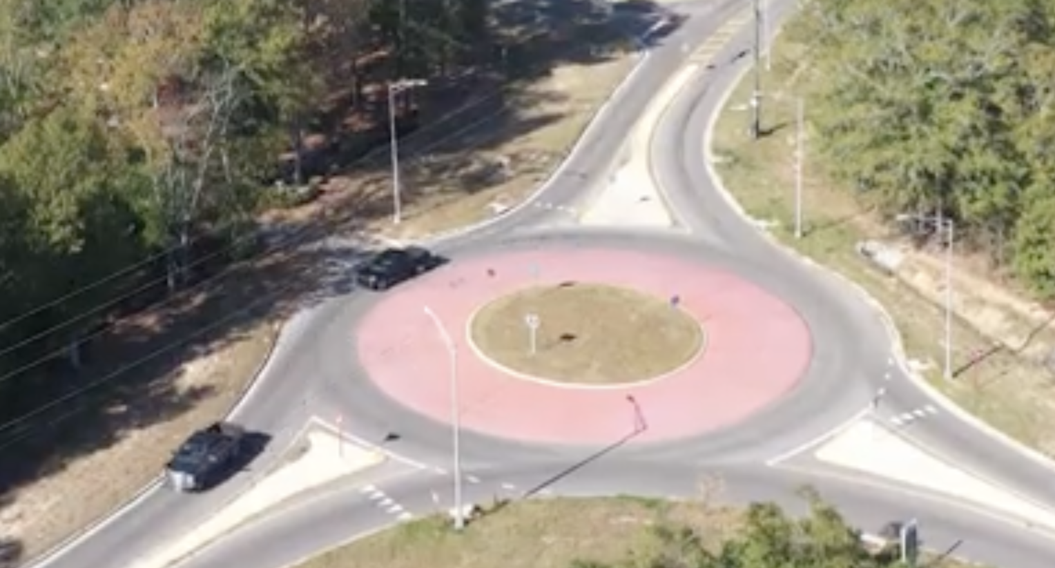
Video: New Roundabout Under Construction at McIver and Old Florence Roads in Darlington County
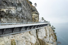
K2b Cantonal Highway
June Issue 2026
.jpg?width=225)