Better in 3D: How 3D Modeling Helped Overcome Complexity in Building the Longest Cable-stayed Bridge in Africa
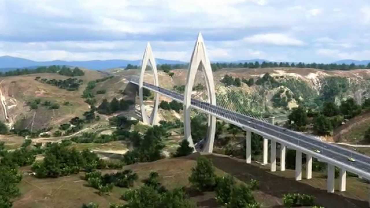
When Morocco’s highway company, Autoroutes Du Maroc (ADM), undertook a highway bypass project in 2010 that would cross the Bouregreg River, they could have built a traditional viaduct. Instead, they set out to construct Africa’s longest and tallest cable-stayed bridge. The resulting project presented unique and complex challenges that called for innovative solutions.
The Bouregreg River runs from the Atlas Mountains to the Atlantic coast between the cities of Rabat and Salé in western Morocco. The bridge spans a kilometer-wide section of the river valley near the Sidi Mohammed Ben Abdallah dam. The larger Rabat motorway bypass project will connect the cities of Fes in the north and Casablanca on the Atlantic coast, allowing travelers to skip the busy capital Rabat. The bypass will alleviate traffic, speed up commerce and transport, and increase road safety in the region.
Design Details
The Bouregreg bridge design actually consists of two successive bridges joined together. The 200-meter access bridge connects from the south side to the main cable bridge, which spans another 742 meters, giving the bridge a total length of just under a kilometer (952 meters.). The two striking pylons, inspired by Islamic architecture, consist of four curved, reinforced caissons converging at the top and joined at the base by a fifth central box. They are spaced 376 meters apart and each is stayed by 183 meter reaching cables. The bridge’s deck consists of two lateral ribs of reinforced concrete connected by metal spacers every four meters, and a reinforced concrete slab 0.25 m thick. The 30.4-meter wide deck is supported by two x 20 pairs of parallel struts spaced eight meters apart, and will have three lanes going in each direction.
The bridge was designed by the French company Setec TPI and STRATES Architects, and involved multiple other players in the engineering and construction process. Due the project’s complexity, French consultants Egis JMI were brought in to do the final design “shop drawings” of the fabrication and structural details including final calculation notes.
Enter Egis JMI
Egis JMI (Jean Muller International, named for the original firm’s founder), part of the larger Egis Group, is based in Paris and operates in Europe, Africa, and Asia, handling infrastructure projects of all types—rail and transport, road, buildings, water and environmental, as well as aviation. Egis JMI is known for their work on the Jacques Chaban-Delmas Bridge in Bordeaux, with its unique vertically lifting middle deck. The firm won the “Grand Prix de la Construction” award in 2013, and the FIDIC Award for “Outstanding Project of the Year” in 2014.
Arnold Ledan, CAD Manager at Egis JMI, who took the lead on this project, says, “Egis JMI was charged with verification of and bearing authority for the accuracy of all dimensions, apart from the principal controlling dimensions shown on the plans.”
On a project of such a grand scale, this is no small undertaking. “Our job,” relates Ledan, “is to immediately advise the engineer of any errors or discrepancies we find while preparing the drawings.” And yes—they identified some issues.
Ledan points out that, in some cases, using traditional 2D drawings is prone to errors. He says, “2D drawings can be disconnected views of a bridge. When you’re dealing with complex 3D geometry like this, it’s difficult to have precise 2D representation capture the design intent.” Additionally, when different 2D views report the same dimension, you must verify the concordance manually.
Better in 3D
Due to the Bouregreg project’s complexity, Egis created a 3D model to determine if the design was in fact feasible, as well as identifying any design or dimension errors that might have gone undetected in 2D drawings.
- Egis JMI used Inventor for flexible bridge modeling, and its ability to dynamically link with Excel and share the library via Vault for collaboration purposes.
- They created the digital model field from the TOPO file in AutoCAD Civil 3D, with recovery of the triangulated land size in AutoCAD.
- They imported and triangulated surface modeling in Inventor.
This approach helped Egis include the specific terrain and its effect on the bridge’s foundations. “Working with the 3D model,” says Ledan, “we were able to identify structural problems in both the pylon and the deck designs, and adapt the design before construction.”
The Pylon Problem
Each pylon consists of four legs joined at the head and foot with two curves. Ledan reports, “We found that the original conception of the pylon heads, with circular pre-stressing cables, was not optimal.” To overcome this shortcoming, “We proposed a design that included a metal box with guiding tubes for the cables.”
Egis’s new design for the cable connection ensured that the head was able to bear the pull of the cables. “In addition,” says Ledan, “the guiding tube mechanism aligned the cables precisely.”
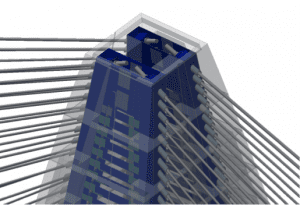
After
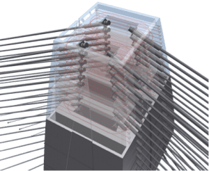
Before
The Deck Dilemma
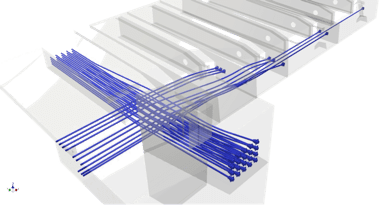 When Egis examined the bridge’s deck design, they identified another issue.
Ledan recalls, “By manipulating the 3D model, we determined that the diameter of the precast cables in their pre-stressed state would create a clash, which had not been evident in the 2D design.”
Egis again used the 3D approach to find a solution. “We ran a clash detection based on minimum tolerance between the cables, and guaranteed zero clash in the revised design.”
Minimizing the Cost of Corrections
The benefits of using a 3D model in this instance cannot be overstated. Ledan points out, “Without the 3D model and a collaborative platform, the design adaptations needed to correct the clashes we identified would have created rework and delays during construction, at considerable cost.”
As a result of Egis’s novel approach, additional cost and work were avoided. Ledan concludes, “This was an incredibly complex project, with over 2,000 drawings generated. And yet, no rework was required for the drawings’ acceptance. The 3D approach allowed us to detect all design flaws in the virtual space before they could propagate to paper—and eventually to the construction site.”
Thanks to Egis JMI’s 3D model shop drawings, the first design submittal was the last submittal. Construction is still underway, and is due to be completed in December, 2015.