Bridge Code: Steel Bridge Design Specifications Revised in New AASHTO Edition

Sponsored by:
Interim revisions to AASHTO LRFD Bridge Design Specifications (7th Edition) were published in 2016 with a few minor revisions to the steel bridge design sections of the specifications. The 8th edition of AASHTO LRFD Bridge Design Specifications is expected to be published later in 2017. As far as steel bridge design is concerned, a major revision to the design of bolted field splices and minor revisions to other sections are expected.
Let’s take a deeper look at the major design checks for steel tub-girders and their technical background.
Cross-Section Proportion Limits
Cross-Section Proportion Limits for tub-girders are covered in Article 6.11.2 of AASHTO LRFD Bridge Design Specifications. In these equations, D/tw is set as the practical limit or web slenderness, and the limitation changes depending on the presence of longitudinal stiffeners attached to the webs. Although the limit for the webs without longitudinal stiffeners is 150, the limit for webs with longitudinal stiffeners is 300.
There are other limitations regarding flange proportioning, which ensures that the flange doesn’t distort after welding to the web. In addition, flanges thicker than the web provide restraints for web shear buckling. The slope of the inclined webs is related to another limitation. Inclination of web plates shall not exceed a 1:4 ratio, and the bottom flanges should extend at least 1 inch beyond the web plates for welding purposes.

Constructability
Constructability checks for tub-girders are covered in Article 6.11.3 of AASHTO LRFD Bridge Design Specifications. In the sections of the bridge where the deck may still be wet, the tub section will be noncomposite. Therefore, without the contribution of the deck stiffness, flanges of the tub-girders may experience high stresses. The top flanges in the positive flexure regions are especially susceptible to buckling during this stage, as it’s very important to simulate and analyze the actual deck placement sequence in the bridge model.
Due to the similarity of the top flanges of I-girders and tub-girders, constructability checks for top flanges of tub-girders are referenced in the I-girder section in AASHTO LRFD Bridge Design Specifications (Article 6.10.3). In the equations in Article 6.10.3, fbu is the bending stress due to major axis bending moment, and fl is the stress due to flange lateral bending. The equations for top flanges in compression are for checking the flange yielding, flange buckling and web bend-buckling.
On the other hand, if the top flanges are in tension, they’re checked for flange yielding. The flange lateral bending stresses are considered in the top flange constructability equations because the deck concrete isn’t hardened, and it’s not fully bracing the top flanges of tub-girders during construction. Discrete lateral bracing is provided by the internal cross-frames and the top flange lateral bracing during construction.
Bottom flanges of tub-girders are checked for flange buckling and web-bend buckling when they’re in compression, and they’re checked for flange yielding when they’re in tension. Tub-girders have very wide bottom flanges, which make them very slender. Slender plates are widely known to be susceptible to buckling. Therefore, longitudinal bottom flange stiffeners may need to be used to reduce the slenderness of the bottom flange by increasing the stiffness of the bottom flange and decreasing its unbraced length.
It’s important to note that when the bottom flange is in tension, its resistance allocated for flexural stresses is decreased due to St. Venant torsion. Typically, the bottom flange tension check does not govern. Also, shear resistance of the webs will be checked during construction in addition to the flexure checks covered above.
Service Limit State
Service Limit State checks for tub-girders are covered in Article 6.11.4 of AASHTO LRFD Bridge Design Specifications, whereas I-girders are covered in Article 6.10.4. According to Article 6.10.4, if the longitudinal tensile stress in the deck does not exceed two times the modulus of rupture of concrete, the deck may be assumed to be fully effective, and the composite section properties can be used for stress calculations. Also, compressive stress in the deck can’t exceed 60 percent of the compressive strength of the deck concrete.
For Service Limit State, both flanges are checked for flange yielding and web bend-buckling. Note that there’s flange lateral bending stress, fl, parameter in Eq.6.10.4.2.2-2, however, it’s only applicable to I-Girder bridges and not tub-girder bridges.
Strength Limit State
Strength Limit State checks for tub-girders are covered in Article 6.11.6 of AASHTO LRFD Bridge Design Specifications. Strength Limit State has different checks depending on the sign of the flexure in the section.
For the sections in positive flexure, it starts with the compactness check for the section. Tub-girder sections can be classified as compact sections if all the following are true:
• The bridge is straight.
• The yield strength of the steel does not exceed 70 ksi.
• The web is not slender (Article 6.11.2.1.2).
• The bottom flange is fully effective (Article 6.11.1.1).
• The section satisfies the girder spacing and overhang requirements specified in Article 6.11.2.3.
The compact sections in the positive flexure regions are permitted to exceed the moment at first yield, however, in continuous spans, moment capacity is limited to 30 percent more than the moment at first yield. On the other hand, noncompact section checks in positive flexure are based on the flange yielding stresses. It’s important to note that St. Venant torsion decreases the bottom flange resistance. For top flanges, St. Venant torsion stresses are resisted by the deck, and it has no effect on top flange resistance.
Checks for the sections in negative flexure are similar to the constructability checks; however, since the deck continuously braces the top flange at the Strength Limit State, flange lateral bending is not a concern. Typically, the buckling of the bottom flange controls this check. As was previously mentioned, bottom flanges of tub-girders are very wide and slender. By adding a longitudinal stiffener to the bottom flange, the stiffness of the bottom flange could be increased, and the slenderness ratio could be reduced.
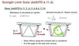
For the Strength Limit State, in addition to the flexure checks, shear resistance of the web also should be checked. St. Venant torsion produces circulatory shear stresses around the tub-girders. Therefore, in addition to the vertical shear forces, shear forces due to St. Venant torsion also should be considered. As shown in the accompanying sketch, although St. Venant torsion decreases the total shear force on one web, it increases the total shear force on the other web. The shear force used in this check should be the shear force along the inclined web.
This column originally appeared in the September/October 2017 issue of Informed Infrastructure. Since then, author Burak Boyaci, P.E., Product Manager for LEAP Bridge Steel at Bentley Systems, spoke with Informed Infrastructure about updates to the AASHTO Bridge Design Specifications, including the field splice design approach and other aspects.
Author

Burak Boyaci
Burak Boyaci, MSc, P.E., is the product manager of LEAP Bridge Steel at Bentley Systems; email: [email protected].
Video: New Roundabout Under Construction at McIver and Old Florence Roads in Darlington County

Bridge Replacement at Amsterdam Centraal Station

June Issue 2026
.jpg?width=225)